Download
1 / 48
500 likes | 697 Views
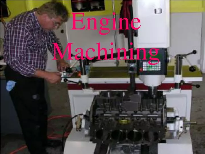
Engine Machining. Decking the Block. The deck of the block should not be warped to insure a sufficient head gasket seal. Concurrently, block deck should be parallel to the main bearing bores.

E N D
Decking the Block • The deck of the block should not be warped to insure a sufficient head gasket seal. • Concurrently, block deck should be parallel to the main bearing bores. • Block deck is checked with a straightedge and a feeler gauge at six different positions, check manufacturers specifications.
Decking the Block • A block that has been “decked” will have it’s surface(s) sanded parallel with the crank bore. Pg.446 • Decking the block will raise static compression.
Cylinder Boring • Cylinders are usually tapered after extensive usage. • Most of the wear will occur at the top of the cylinder, just under the ridge. • Though not highly advised, the ridge may be removed with a “ridge-reamer” for piston removal. • The engine must be “bored” and new pistons fitted if the cylinder is out of specification.
Cylinder Boring • Maximum bore oversize is determined by cylinder wall thickness and piston size availability. • An ultrasonic test may be performed to determine cylinder wall thickness. • Cylinders should be machined to the smallest oversize possible.
Cylinder Boring Calculating oversize diameter … • One method is to factor the maximum amount of taper, double it, and add .010in. This will give you your piston size.
Cylinder Boring • A boring bar is used to bore the cylinder diameter. • The cylinder must be perpendicular to the crank-shaft bore before boring is attempted. • Main bearing caps must be installed and torqued to specifications prior to boring.
Cylinder Boring • Cylinders are bored .002” - .010” under the finish bore size. • Torque plates should be used on the deck for bores larger than .030”. Pg.451 • Boring leaves a finish too rough for service.
Cylinder Honing • The cylinder finish is, in effect, sanded to a proper finish and/or size. • Deglazing hone – removes the hard surface glaze remaining after normal engine usage. • A flexible hone that follows the shape of the cylinder wall. • Ball type • Stone type
Cylinder Honing • Sizing hone – used to finish a bore procedure, straighten cylinder taper and provide a suitable surface for the piston rings. • While size honing, the cylinder must constantly be checked with a bore gauge to check for size and taper. • Cylinders will generally hone quicker closer to the deck of the block.
Cylinder Honing • While honing, it is important to constantly move the hone in a vertical motion. • This vertical motion insures that a cross-hatch finish is left. • The crosshatch should be between 20 and 60 degrees. • Too little crosshatch will cause excessive ring wear. • Too much may effect compression.
Cylinder Honing • Plateau honing – using different grit stones, in succession, to achieve proper size and finish. May be done in two or three steps (different size stones). • The grit of the finishing stone will be determined by the ring composition. • Chrome - #180 grit • Cast iron - #200 grit • Moly – #220 grit
Cylinder Honing • The top edge of the cylinder should be chamfered prior to honing. • Cylinders are finish honed to specific piston diameters to insure proper clearances. • The finished hone should be within .0005” of desired size and taper
Cylinder Honing • The cylinder must be thoroughly cleaned after any honing is done to remove dirt and abbrasives. • This is done with a brush, soap and water. • The cylinder can be wiped with a clean, dry cloth to check cleanliness of the walls.
Lifter Bore Honing • Lifter bores are deglazed with a finishing stone to remove wear patterns.
Main Bearing Bores • Final machining of the main bearing bores (align bore) and cam bearing bores is done with the main caps torqued. • FOR THIS REASON, MAIN CAPS ARE NOT INTERCHANGEABLE NOR UNIDIRECTIONAL.
Main Bearing Caps • Designs include … • A Girdle design. (pg. 440 fig. 19-24). • A two bolt main cap (pg. 439 fig. 19-21). • A four bolt main cap (pg. 439 fig. 19-22). • Mostly high-performance and truck designs.
Main Bearing Caps • A six bolt main cap design. (pg. 440 fig.19-43) • A bedplate design (pg. 435 fig. 19-10). • Attaches to the bottom of the block and supports the crankshaft.
Main Bearing Caps • The main bearings are held into place by the main bolts and enlarged areas of the block called bosses.
Main Bearing Bores • M.B.B.s may elongate over time and become egg-shaped (pg. 441 fig. 19.27). • This out-of-round can be checked with a bore gauge in 3 different positions. 0.0005 variance is considered acceptable. • The main bearing bore not contained within the cap is called the saddle. • The saddle will be part of the engine block in most cases.
Main Bearing Bores • If the M.B.B. is measure outside of limits, the saddles can be checked with a straightedge and feeler gauge (pg. 441 fig. 19-28). • If the saddles are within limits, the face of the caps may be block sanded to compensate for out-of-round.
Main Bearing Bores • The main bearing bores must then be align honed to restore its symmetry. (pg 458 sequence). • Note: the depth of the saddle cannot be altered because this will alter the centerline distances between the crank and cam.
Cylinder Sleeves • Cast iron or steel sleeves are installed at the factory on some aluminum engine blocks. • They may be cast or pressed into the block. • Silicon-aluminum blocks have no sleeves installed. • Pistons with zinc-copper-hard iron coatings are used in this design (Porsche 944).
Cylinder Sleeves • A dry sleeve is completely supported by the engine block and does not come in direct contact with the coolant passages (Saturn, Ford, Northstar (pg. 434)). • A wet sleeve is in direct contact with the water passages. Therefore, they must be thicker to withstand combustion pressures (Cadillac 4.1, 4.5, 4.9).
Cylinder Sleeves • A sleeve may be installed into a cast iron block if a cylinder is badly damaged. • Typically, the cylinder is bored to the exact outside diameter of the sleeve. A ridge is left at the bottom of the cyl. To support the sleeve. • The block is then heated and the sleeve frozen to aid installation.
The crankshaft must be ground if not within specification • Generally speaking, if the groves on the crank journal can be felt with your finger-nail, it should be ground