Download
1 / 48
490 likes | 1.39k Views
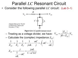
Figure 8.1 A circuit used to illustrate the natural response of a parallel RLC circuit. Figure 8.2 A circuit used to illustrate the step response of a parallel RLC circuit. Figure 8.3 A circuit used to illustrate the natural response of a series RLC circuit.

E N D
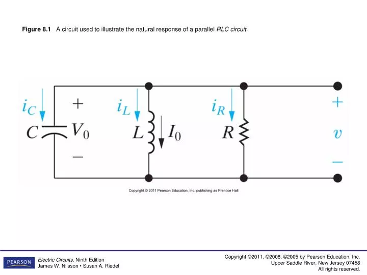
Figure 8.1 A circuit used to illustrate the natural response of a parallel RLC circuit.
Figure 8.2 A circuit used to illustrate the step response of a parallel RLC circuit.
Figure 8.3 A circuit used to illustrate the natural response of a series RLC circuit.
Figure 8.4 A circuit used to illustrate the step response of a series RLC circuit.
Figure 8.5 A circuit used to illustrate the natural response of a parallel RLC circuit.
Figure 8.11 A circuit used to describe the step response of a parallel RLC circuit.
Figure 8.14 A circuit used to illustrate the natural response of a series RLC circuit.
Figure 8.15 A circuit used to illustrate the step response of a series RLC circuit.
Figure 8.18 Two integrating amplifiers connected in cascade.
Figure 8.20 Cascaded integrating amplifiers with feedback resistors.
Figure 8.21 The circuit diagram of the conventional automobile ignition system.