Download
1 / 19
190 likes | 363 Views
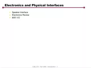
Electronics System Overview and Interfaces. Rick Cook Electrical Systems Engineer. Electronics Configuration. Electronics Provide regulated power to instrument Control and readout the Focal Plane Modules (FPM) Control of calibration source motor Control and power for mast adjustor

E N D
Electronics System Overview and Interfaces Rick Cook Electrical Systems Engineer
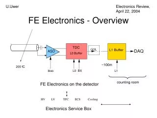
Electronics Configuration • Electronics • Provide regulated power to instrument • Control and readout the Focal Plane Modules (FPM) • Control of calibration source motor • Control and power for mast adjustor • Control, readout and power for laser metrology system • Control of instrument operational thermal heaters, thermistors • Control and readout PMD experiment • Single command/data interface with S/C through CEB • Operate off 30V power from S/C
Design Overview • Design/implementation emphasizes manufacturability, reliability and serviceability • Access to boards, detectors • Central Electronics Box (CEB) [4 boards plus backplane] has card cage design with heat-actuated connectors for easy removal/servicing • Minimize internal wiring and harnessing • Minimize electronics parts types and count • Rely where possible on familiar parts, connectors, processes • Use same parts types as STEREO, ACE where possible, same foundry for ASIC as HEFT • All lab detector test benches utilize same MISC processor architecture as flight instrument • Enables/requires early firmware/software development • Establishes data formats early
Electronics • Eleven distinct boards in FP&E subsystem • Excludes laser metrology boards (discussed yesterday) and mast adjustor
Design Overview • Detector carrier board, motherboard, FP MISC board, CEB logic board, OBEB boards designed and implemented by Caltech • PMT base board utilizes HVPS design from UCB (preliminary layout, breadboard by UCB) integrated onto Caltech board with remaining circuitry • LVPS, Post Reg, and CZT HVPS designed by Dean Aalami (Space Instruments-SI) • Long collaboration with SI on ACE/Stereo • Design, layout, EM test, reliability analyses by SI • parts procurement, flight board procurement, and fabrication by Caltech • Same successful model followed on ACE and STEREO
Design/test Flow Test/rework/test R. Cook B. Kecman J. Burnham V. Nguyen Layout J. Burnham V. Nguyen Preliminary design and schematic R. Cook Detailed schematic J. Burnham V. Nguyen Layout Review C. Derksen (JPL) EM Fab Vendor L. Hernandez J. Olivares Parts identification EM and flight B. Kecman J. Valenzuela Formal parts stress analysis J. Burnham Parts Procurement, EM and Flight B. Kecman, J. Valenzuela, J. Olivares Flight Board Fabrication Vendor L. Hernandez, JPL Flight Board Test R. Cook, B. Kecman, J. Burnham, V. Nguyen Staking, Conformal Coating JPL
Board Status FP&E Board development status
Reliability Analyses • JPL review/requirements discussed in SMA presentation tomorrow • PSAs completed prior to flight board procurement, and typically before EM board procurement • CIT engineer (J. Burnham) performes analysis using JPL spreadsheet or annotated schematic • A separate CIT designer (R. Cook) reviews analysis • Select analyses reviewed by JPL • WCTA for FPGAs will be completed upon final flight part FPGA design/burn in • Flight ACTELs costly, not available until 8/09 • To mitigate design risk, clock margin tests performed on EM parts • Two flight-quality parts received - clock margin tests will be performed on EM boards with these parts
Electronics Power Total electronics power: XX W : FP&E power dominated by thermal
Grounding Approach • Describe the grounding philosophy/approach here with attention to sensitive signals, avoiding ground loops, ……..
Overall Grounding Diagram • Insert overall grounding diagram here
Bench Grounding Diagrams • Insert grounding diagrams for benches here
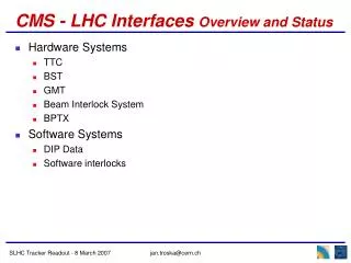
Instrument to S/C Electrical Interfaces • Interfaces with S/C controlled by EICD (JPL D-41874) • signed and under configuration control • Command and data interfaces with S/C go through CEB • Command – 57.6 kbaud serial • Data – 460.8 kbaud three wire serial (clock, data, gate) • Reset -- 100 msec pulse • Frame Sync – 1 msec pulse, once per second • Other interfaces • Motor controller - managed by JPL, not covered in this review • Primary operational power: 30 V to CEB for distribution (fused or not - anything interesting to say?) • Survival heater power: 30 V • S/C monitored thermistors
MUC to Instrument • CEB interfaces to S/C Mission Unique Card (MUC) • RS422 interface for commands and data • Describe data enable, synch or anything else - is it synchronous, asynch, quasisynch……
Data Formats, Telemetry Protocols Science, Metrology, HK, and Command responses are formatted into CCSDS packets by CEB MISC Raw and packetized instrument data formats are defined in Instrument Telemetry Format Document Packet headers, APIDs, packet sizes, transfer protocols, etc. have been negotiated with S/C team, and documented in Instrument/Spacecraft ICD (JPL D-41874), and are under configuration control Basic packet format
Data Transfer • Packet time stamps, checksums inserted by CEB • no requirement on S/C to examine/modify contents • Realtime packets contain HK, detector leakage currents, Cmd-responses, and subset of science and metrology data • 4 pkts/s max • Recorder packets contain all science, metrology, PMD data • Throughput limited by S/C VR capacity and availability of downlink passes • Instrument maximum science data rate is commandable Basic data flow from instrument to S/C memory to ground
Command Format • S/C unpacks instrument telecommand packets, routes contents to CEB via instrument cmd serial interfaces per ICD protocols • Instrument command responses are encapsulated in CCSDS packets with an APID as defined in ICD Command transfer format
Summary • Design approach follows CIT/SRL methodology proven most recently on ACE (CRIS&SIS) and STEREO • Designs and schematics for all circuits completed • Early completion and test of FPM EM gives high confidence • Most critical circuits tested and working as a system: • Flight ASIC • PMT base • FPM MISC • Detector carrier board • Detector motherboard