Download
1 / 19
190 likes | 309 Views
Recent Experimental frequency maps at SLS and BESSY. M. Belgroune PhD position (10/2001-10/2004). Collaboration with P. Kuske Collaboration with A. Streun, M. Munoz, M. Boege. Contents. Recent Experimental Frequency Maps at SLS. On momentum dynamics.

E N D
Recent Experimental frequency maps at SLS and BESSY M. Belgroune PhD position (10/2001-10/2004) Collaboration with P. Kuske Collaboration with A. Streun, M. Munoz, M. Boege
Contents • Recent Experimental Frequency Maps at SLS On momentum dynamics optics (20.38, 8.16) with zero chromaticities optics (20.38, 8.16) with high chromaticities 2. Recent Experimental Frequency Maps at BESSY On momentum dynamics optics (17.85, 6.74) with zero chromaticities Nice surprise ! 3. Open discussions
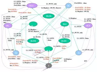
Collaboration with SLS April 2002 : First FMA Meeting with SLS team and first FM simulations for the bare lattice at (20.38, 8.16) Decision to modify one of the injection kickers to allow experimental FM measurements (simultaneous horizontal and vertical kicks) Summer 2003 : Installation of the pinger Magnet and first tests were promising Thanks to M. Munoz a software architecture based on a server/client model has been developed and allows to centralize the tunes evaluation (see M.Munoz presentation for experimental set details) Thanks to A.Streun an IDL on line application has been developed and resonances could be immediatly identified after FM acquisition March 2004 : The pinger Magnet was ready for use and invitation to participate to the first FM measurements Data Analysis is still in progress and first attempts are shown here
H V Working conditions SLS 9 families of sextupoles (2 harmonics) Pinger Synchronisation with a train of 30 bunches (I= 10mA 0.3mA/bunch) Pinger calibration using a scraper For the zero chromaticities mode (experimental verification of both chromaticities x = 0.05 z = -0.07) For the high chromaticities mode (experimental verification of both chromaticities x = 3.82 z = 4.93)
Working point (20.38, 8.16) zero chromaticities mode Frequencies determination using FFT NAFF implemented but needs some modifications Range of amplitudes covered (x, z) = (5.3mm, 2.8mm) with a square root law Max current in kicker (1800A, 1200A) Only 5.3 mm in horizontal Very small decoherence on 516 turns Sampling 50*25 Very finesampling of the small region possible to cover with the kicker limitation (example in horizontal some 10-1 mm at the begining then some 10-2 mm)
Experimental frequency map at(20. 38, 8.16) and zero chromaticities SLS On momentum Very nice resonances revealed as desertions thanks to the fine sampling Theoritical working point
Experimental frequency map at(20. 38, 8.16) and zero chromaticities SLS 17 order non systematic These resonances are of very high order 19 order skew One has to go to higher orders to identify the others ! Resonances up to 19 order
Experimental frequency map at(20. 38, 8.16) and high chromaticities SLS On momentum Very nice resonances revealed as desertions thanks to the fine sampling Theoritical working point Sampling 36*29 high chromaticities means x 4, z 5
Experimental frequency map at(20. 38, 8.16) and high chromaticities 19 order systematic SLS On momentum 17 order non systematic These resonances are of very high order Resonances up to 19 order
The reinjection is not yet automatic The X and Z positions are calculated on the BPM electronics (time consuming) An other limitation on the kicks rate (1Hz in this case) & triggers in addition to tunes calculation and storage Observation of a strange coupling which necessitates more investigations : is the vertical kick pure or is the V-pinger rotated ? Phase space reconstruction : particle position in turn n+1 as a function of the position in turn n for a very small horizontal kick (almost 0) and increasing vertical kick With courtesy of Andreas Streun
Future important developements (see also M. Munoz presentation) Double the current in the kicker magnet for the horizontal kicks factor 4 on the amplitudes possibility to cover the whole dynamic aperture ( 20 mm) Acquire a second turn by turn BPM and allow on line phase space representation
Collaboration with BESSY December 2002 : First FMA simulations for the bare lattice at (17.85, 6.74) with positive chromaticities (routine operation mode) 2003 : Thanks to P. Kuske developments have been done to allow experimental frequency maps measurements November 2003 : P. Kuske showed the first experimental frequency maps January 2004 : Invitation to participate to the FM measurements Data Analysis is still in progress and first attempts are shown here So Keep your ears and eyes quite open, there is a nice surprise to see !
Working conditions BESSY Pinger Synchronisation with a train of 50 bunches (I= 5mA 0.1mA/bunch) Pinger calibration using a scraper For the zero chromaticities mode (experimental verification of both chromaticities)
BESSY Non negligeable decoherence on 500 turns A sight on the control panel for frequency maps acquisition in the BESSY II control room With courtesy of Peter Kuske
Experimental frequency map at(17. 845, 6.74) and zero chromaticities BESSY On momentum Can you see something ?! Colours there represents horizontal tunes dependance for fix vertical amplitude
A B C D FIRST NICE COLOUREDEXPERIMENTAL FREQUENCY MAP The idea is to use the fourth electrode of the BPM to record the turn by turn current. The three others are reserved to the X and Z transverse positions For turn by turn X and Z positions record Definition of a loss rate as For turn by turn current record Which can be coded from blueNo current loss to redmaximum currentloss This can be stored for each couple of H and V kicks
FIRST NICE COLOUREDEXPERIMENTAL FM at(17. 845, 6.74) and zero chromaticities BESSY On momentum At the location of the low beta section BESSY Aperture at the entrance of the machine = 17.4mm * 4mm Which has to be compared to a good model reproducing the machine behaviour
FIRST NICE COLOUREDEXPERIMENTAL FM at(17. 845, 6.74) and zero chromaticities BESSY On momentum At the location of the low beta section
Next Step :looking into the model ………. Special Thanks to the SLS and the BESSY teams for the nice and very interesting collaborations Special Thanks also to the SLS team for allowing the use of the IDL licence on distant machine Special thanks to R. Nagaoka for interesting discussions and to M.E Couprie for help