Download
1 / 17
200 likes | 539 Views
<LG Display- 연세대학교 산학협력 > 2011. 04 . 20. Low-temperature processed zinc tin oxide TFT. 연세대학교 정보표시재료연구실. 백홍구 , 유영범 , 박지호. ㅋ. Zinc Tin Oxide – advantages Positive Bias stress stability Negative bias illumination stress stability Chemical stability Scratch resistance Smooth surface.

E N D
<LG Display-연세대학교 산학협력> 2011. 04 . 20 Low-temperature processed zinc tin oxide TFT 연세대학교 정보표시재료연구실 백홍구, 유영범, 박지호
ㅋ • Zinc Tin Oxide – advantages • Positive Bias stress stability • Negative bias illumination stress stability • Chemical stability • Scratch resistance • Smooth surface
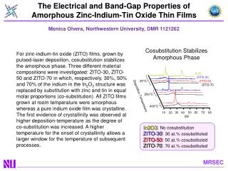
ㅋ • Sol-gel processed Zinc Tin Oxide Conventional hydrolytic sol-gel process “Hydrolysis and condensation” High decompositiontemperature of Sn(OH)4
ㅋ • Nonhydrolytic sol-gel processed Zinc Tin Oxide “Ester elimination process” Zn(OAc)2 + Sn(OtBu)4 → Zinc tin oxide + tBuOAc Zinc tin oxide Tert-butyl ester Zinc acetate Tin tert-butoxide “Precursor double layer” Prevention of reaction between precursors Zn(OAc)2 Zinc tin oxide Annealing Sn(OtBu)4 SiO2 (200nm) SiO2 (200nm) Si Si
ㅋ • Precursor double layer Zn(OAc)2 Sn(OtBu)4 Uniform coating Substrate Sn(OtBu)4 Dissolve bottom layer Poor coating Zn(OAc)2 Substrate
ㅋ • Precursor double layer Uniform coating Dissolve bottom layer Poor coating
ㅋ Zn(OAc)2 0.25M 0.15M 0.2M Sn(OtBu)4 0.02M 0.025M 0.033M
ㅋ • Annealing time 300°C, 2hr 300°C, 3hr 300°C, 1hr
ㅋ • Annealing temperature 250°C 270°C 300°C 330°C
ㅋ • Annealing ambient Dry N2 Dry air Dry O2 Wet air
ㅋ 0.033M Tin tert-butoxide No mobility improvement 0.15M Zinc acetate 0.2M Zinc acetate UV 5min
ㅋ • Optimum device (2-precursors) 0.033M Tin tert-butoxide 0.2M Zinc acetate 300°C, 3hrs
ㅋ • 3-precursors double layer “2-Precursors double layer” “3-Precursors double layer” Zn(OAc)2 Zn(OAc)2 + Sn(OAc)4 Sn(OtBu)4 Sn(OtBu)4 SiO2 (200nm) SiO2 (200nm) Si Si
ㅋ 0.2M Zinc acetate:Tin(IV) acetate = 4:1 0.03M Tin tert-butoxide 0.035M Tin tert-butoxide 0.04M Tin tert-butoxide 0.15M Zinc acetate:Tin(IV) acetate = 4:1 0.03M Tin tert-butoxide 0.035M Tin tert-butoxide 0.04M Tin tert-butoxide
ㅋ • Optimum device (3-precursors) Improved S.S. Vth ~ 0 Increased IOff 0.15M Zinc acetate:Tin(IV) acetate = 4:1 0.035M Tin tert-butoxide 300°C, 3hr Annealing
ㅋ • Future works • Improving S.S. voltage • Gate dielectric (ex. ZrO2) • N2 Pre-baking • Microwave annealing
ㅋ • Supporting (Wet annealing)