Download
1 / 23
240 likes | 370 Views
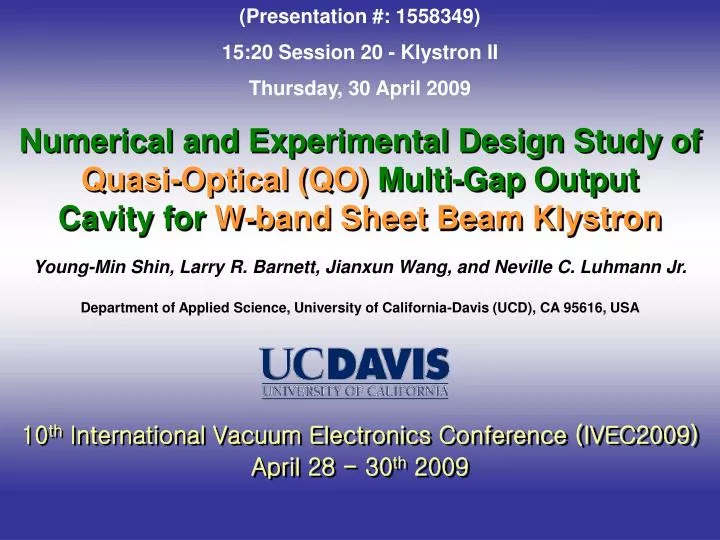
(Presentation #: 1558349) 15:20 Session 20 - Klystron II Thursday, 30 April 2009. Numerical and Experimental Design Study of Quasi-Optical (QO) Multi-Gap Output Cavity for W-band Sheet Beam Klystron. Young-Min Shin, Larry R. Barnett, Jianxun Wang, and Neville C. Luhmann Jr.

E N D
(Presentation #: 1558349) 15:20 Session 20 - Klystron II Thursday, 30 April 2009 Numerical and Experimental Design Study of Quasi-Optical (QO) Multi-Gap Output Cavity for W-band Sheet Beam Klystron Young-Min Shin, Larry R. Barnett, Jianxun Wang, and Neville C. Luhmann Jr. Department of Applied Science, University of California-Davis (UCD), CA 95616, USA 10th International Vacuum Electronics Conference (IVEC2009) April 28 - 30th 2009
Acknowledgements • We wish to acknowledge informative discussions with • Dr. Glenn P. Scheitrum and Dr. Aaron Jensen on the SLAC WSBK • We also wish to Dr. Ali Farvid at the Stanford Linear Accelerator Center • (SLAC) for his generous help, advice, and assistance in setting up the • electroforming system, and to acknowledge informative discussions with • Dr. Frank Yaghmaie, Director of the Northern California • Nanotechnology Center (NCNC) in the University of California – Davis • (UCD) This work is supported by the Marine Corps Systems Command (MCSC), Grant No. M67854-06-1-5118.
Outline • Motivation and Objectives • Electron Gun and Focusing Magnet • QO Output Cavity Design and Analysis • Simulation Examination and Cold-Test • Full Tube Design (AJDISK) and PIC Simulation (MAGIC3D) Analysis • UV LIGA Microfabrication • Summary and Future Plans
Motivation • Develop a transportable, modular system, employing four novel W-band Sheet Beam Klystron (SBK) devices (each capable of 2.5 kW of average power) and producing a minimum of 10 kW of 95 GHz radiation. Higher powers can be produced by adding more SBKs and combining their output powers either by waveguide multiplexing, or in space. Original SLAC MURI Concept
Original SLAC MURI WSBK Design Parameters Beam voltage: 74 kV Beam current: 3.6 A Peak power: 50 kW Average power: 2.5 kW Efficiency: 20% Gain: 40 dB Brillouin Magnetic field: 1000 Gauss (RMS) Number of cavities: 8 Circuit length (wg to wg): 9 cm Beam size (elliptical): 6 mm x 0.5 mm (12 : 1) Drift tube size (rectangular): 8 mm x 0.72 mm
PCM Sensitivity Magnetic Anode Body Windows: High VSWR Need for Tuners Input Cavity: Correctly Designed/Incorrectly Fabricated WSBK Problems Output Cavity: Incorrectly Designed
Full Peak Power WSBK Demo Tube • Seven gap velocity tapered output circuit with three gaps in • other cavities • MAGIC 3-D simulations predicted • stability and 50 kW peak output • Gun redesign: the original beam stick gun which produced high efficiency (91 %) • transport was extremely sensitive toalignment ( 0.002” vertical misalignment would • lose40% of the beam in the gun). The anode aperturewas therefore • opened to reduce the anode hole effects • Magnet stack redesigned. • Summary of Prototype WSBK Test Results Maximum beam transmission of 78 % at full design voltage and cathode current-attributed to magnetization of the gun weld ring resulting in beam rotation** Maximum output power of > 11 kW and ~ 48 dB gain observed using sensitive external adjustments of the shunts and cavity tuning using retrofitted cavity tuners. Low output is (as indicated by the test data) due to a combination of poor output coupling involving higher modes, field cancellation at the design frequency, beam and bunch formation, and cavity mistuning. *Summary of initial tests at SLAC and subsequent tests at UC Davis. **Magnetization problem eliminated by proper choice of stainless steel
Amelioration of Technical Issues (1) Anode Flange Magnetization • Replace 304L S.S. with 310 S.S. which cannot be magnetized • Carry out complete 3D Gun and Magnetic field (re-)simulations to verify/modify design using CST Particle-Studio, Advanced Charged-particle Design Suite from Field Precision, and Ansoft Maxwell 3D simulation packages. • Independent modeling assessment by Stan Humphries of Field Precision (2) Incorrectly Machined Input Cavity • Proper input cavity design/fabrication eliminates/ameliorates mode competition problem (3) Incorrectly Designed Output Cavity (7-Gap) • Re-design the output cavity Quasi-Optical (QO) cavity (4) Incorporation of cavity tuners (5) Extensive MAGIC3D simulations to determine optimum design
QO Cavity Design and Sensitivity Analysis • Original 7-Gap Output Most critical dimension: cavity height (dy)
Replacement of WSBK Output Cavity (7-Gap QO) • Original 7-Gap Output • Pocket Machining • QO Output Circuit • Assembled Circuit • QO Circuit Assembly • Brazing Assembly
3-Gap 2-Mode QO Output Cavity Being Installed in Modified Tube
Signal Response and Eigenmode Analysis • Port-to-Port Transmission and Reflection Coefficients (S21 and S11) - FDTD simulation (CST MS) - - Experimental measurement - Total Q (Qt) of the operation TE10 mode (2-mode) of 95.4 GHz is about 450 • Eigenmodes of Multi-Gap QO Cavities f0 (unloaded) = 95.3GHz fL (loaded) = 95.3504GHz Q0 = 1652 Qe = 621 Qtot = 451 f0 (unloaded) = 95.3527GHz fL (loaded) = 95.4074GHz Q0 = 1665 Qe = 646 Qtot = 465 f0 (unloaded) = 95.3731GHz fL (loaded) = 95.385GHz Q0 = 1663 Qe = 655 Qtot = 467 - 4-Gap QO Cavity - - 3-Gap QO Cavity - - 5-Gap QO Cavity - Young-Min Shin, Larry R. Barnett, and Neville C. Luhmann Jr. “Quasi-Optical Output Cavity Design for 50kW Multi-Cavity W-Band Sheet Beam Klystron”, IEEE Trans. Elec. Dev. (submitted, 2009)
QO WSBK Tube Design • AJDISK Simulation Result of Optimized WSBK Tube Design
MAGIC3D Simulation of Full Circuit • Multi-Cell (Export-Import) MAGIC3D Simulation - Input Power and Frequency Spectrum - 1-Port Driving (~ 18.2 mW) - Output Power and Frequency Spectrum - 53 kW 2 × 26.5 kW = 53 kW Beam Voltage = 74 kV Beam Current = 3.6 A Input Frequency = 94.5 GHz Input Power = 18.2 mW Output Power = 53 kW ( = 2 × 26.5 kW) Efficiency = 20 % Gain = 64.64 dB 94.64 94.85 94.5 95.6 94.5 94.64 94.5 94.82 Units: GHz
Parameter Sweep of QO-WSBK Models (Conductivity: = 5.8 × 10⁷ [-1m-1]) 2-Mode (f = 94.5GHz) 2-Mode (f = 94.5GHz) 2-Mode (f = 94.5GHz) 2-Mode (f = 94.5GHz) 2-Mode (f = 94.5GHz) 2-Mode (f = 94.5GHz)
3-Gap Intermediate Cavities (MAGIC3D) • Time History of Output Power - 3-Gap Output Cavity - - 7-Gap Output Cavity - - 5-Gap Output Cavity -
Single Gap Intermediate Cavities:MAGIC3D • Time History of Output Power - 3-Gap Output Cavity - - 7-Gap Output Cavity - - 5-Gap Output Cavity -
Demountable Tube Concept for Hot-Tests • Body of the Demountable Tube (currently being machined) • Assembly of the Demountable Tube • Cover with a gold seal (machining in progress) • Support for the cover
UV LIGA Fabrication of QO WSBK Circuit • KMPR UV Lithography Patterning - UV lithography fabricated mold structure (thickness: ~ 450 m) - • Electroplating and Mold Removal • Lapping and Polishing
Summary and Future Plans 1. Summary - Electron gun and magnet being redesigned Beam transport simulation is underway PCM Magnetic field is being measured - QO output cavity has been designed Dimension parameters optimized Dimensional sensitivity analysis done Cold-test and signal response simulation done - Full Power WSBK tube has been redesigned Tube design finished using AJDISK MAGIC3D simulation verification done Parametric analysis done - UV LIGA Fabrication Multi-Step UV LIGA development is underway 2. Future Plans - Full WSBK circuit engineering design - Demountable tube design - Hot-Test