Download
1 / 1
30 likes | 255 Views
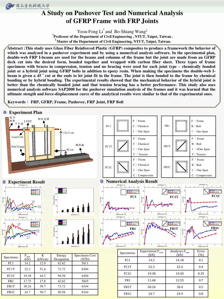
反力剛架. 側向支撐. LVDT. 千斤頂. 122.5 cm. Load Cell. 鋼床板. Dial Gauge. 40 cm. A Study on Pushover Test and Numerical Analysis of GFRP Frame with FRP Joints Yeou-Fong Li 1 and Bo-Shiang Wang 2. 1 Professor of the Department of Civil Engineering , NTUT, Taipei, Taiwan .

E N D
反力剛架 側向支撐 LVDT 千斤頂 122.5 cm Load Cell 鋼床板 Dial Gauge 40 cm A Study on Pushover Test and Numerical Analysisof GFRP Frame with FRP Joints Yeou-Fong Li1and Bo-Shiang Wang2 1Professor of the Department of Civil Engineering , NTUT, Taipei, Taiwan . 2 Master of the Department of Civil Engineering, NTUT, Taipei, Taiwan. Abstract :This study uses Glass Fiber Reinforced Plastic (GFRP) composites to produce a framework the behavior of which was analyzed in a pushover experiment and by using a numerical analysis software. In the specimental plan, double-web FRP I-beams are used for the beams and columns of the frame but the joint are made from an GFRP deck cut into the desired form, bonded together and wrapped with carbon fiber sheet. Three types of frame specimens with braces in compression, tension and no bracing were used for each joint type – chemically bonded joint or a hybrid joint using GFRP bolts in addition to epoxy resin. When making the specimens the double-web I-beam is given a 45 ° cut at the ends to let joint fit in the frame. The joint is then bonded to the frame by chemical bonding or by hybrid bonding. The experimental results showed that the mechanical behavior of the hybrid joint is better than the chemically bonded joint and that tension bracing has a better performance. This study also uses numerical analysis software SAP2000 for the pushover simulation analysis of the frames and it was learned that the ultimate stength and force-displacement curce of the analytical results were similar to that of the experimental ones. Keywords: FRP, GFRP, Frame, Pushover, FRP Joint, FRP Bolt • Experiment Plan • Numerical Analysis Result • Experiment Result FC1C FC1 FC1T FB1C FB1T FB1