Download
1 / 13
130 likes | 286 Views
Introduction to UMB TM Air Interface Upper Layers. Source : TSG-C WG 2 Abstract : This contribution presents an introduction to UMB upper layers. Ultra Mobile Broadband™ and (UMB™) are trade and service marks owned by the CDMA Development Group (CDG). Design goals.

E N D
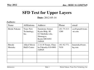
Introduction to UMBTM Air Interface Upper Layers Source: TSG-C WG 2 Abstract: This contribution presents an introduction to UMB upper layers. Ultra Mobile Broadband™ and (UMB™) are trade and service marks owned by the CDMA Development Group (CDG).
Design goals • Efficiently support OFDMA MAC/Phy • Fully support centralized as well as distributed access networks • Streamline inter-access network interfaces • Continue to support fast layer 2 handoff • Seamless handoff across air interface revision boundaries • Apply lessons learnt from EV-DO
UMB efficiently supports centralized access network • AT maintains separate protocol stack for each AN in the Active Set • Each protocol stack is called a “Route” • Extension of EV-DO Route A/B concept • Each BSC is a separate AN No coordination of RoHC/EAP/RLP/Connection state between BSCs
UMB efficiently supports distributed access network • AT maintains separate protocol stack for each AN in the Active Set • Each cell is a separate AN No coordination of RoHC/EAP/RLP/Connection state between eBSs
UMB simplifies the inter-AN interface by requiring the AT to support multiple Routes • Each eBS in the Active Set uses a separate data Route • No need to transfer RLP and header compression state between eBSs • Traffic flowing between an eBS and the AT can be tunneled through the serving eBS • Support fast and seamless re-pointing between cells • Each eBS in the Active Set could use a separate Personality • Seamless handoff across air interface revision boundaries • Signaling messages of protocols between an eBS and the AT can be tunneled through the serving eBS • The eBS which acts as a tunnel need not interpret the tunneled messages • No protocol conversion between eBSs • No eBS has to maintain Connection state of other eBSs in the Active Set • No need to synchronize Connection state across eBSs • UMB reverse link allows manycast • AT can send a packet once over the air and address it to multiple ANs Simple inter-eBS interface leads to standardized, inter-operable implementations
Anchor Route • One of the protocols stacks is designated the Anchor Route • Anchor Route is retained when the AT goes idle • Other Routes are torn down • Anchor Route determines idle state behavior • UATI points to the AN that hosts the Anchor Route • Upon connection set up, AT tunnels priority data the Anchor Route through the serving Route • Data can flow before serving Route fetches the session • Useful for applications with stringent call set-up latency requirements
Requirements on inter-AN interface • Inter-AN interface must support • Tunneling of layer 2 packets • Tunneling of layer 3 packets • Session transfer • Other functions such as paging, neighbor discovery etc. • Inter-AN interface need not support • One AN in control of connection state at another AN • Interpretation/translation of tunneled packets by serving AN • Transfer of RoHC/Connection/RLP state
UMB layering reduces the number of protocols in the data path • Application Layer: Signaling Application, IP, RoHC, EAP, inter-technology tunneling etc. • Radio Link Layer: RLP and associated protocols • MAC Layer: Packet Consolidation Protocol and control of Physical Layer channels • Physical Layer: defines characteristics of air interface channels • Security Functions: protocols for ciphering, message integrity, and key exchange • Route Control Plane: controls the creation and maintenance of air interface protocol stacks, one for each eBS • Session Control Plane: provides session negotiation • Connection Control Plane: controls the Connection between the AT and an eBS
Data Path Packets may be transmitted over the air or tunneled through the serving Route
UMB performs ciphering in RLP • Ciphering is located in RLP • Ciphering is applied to RLP fragments before addition of RLP header • Advantages of ciphering in RLP • Ciphered packets are tunneled through serving eBS • Source eBS and AT tunnel ciphered packets through serving eBS • Serving eBS cannot interpret the packets • Low latency for push-to-X applications • AT sends priority data to the anchor eBS without requiring serving eBS to fetch the session • Lower AT implementation complexity compared to ciphering above RLP • Ciphering can be performed in the access terminal modem without having to re-assemble upper layer packet • Possible software-based ciphering implementation at the AN • Encryption mask can be pre-computed in software • No header overhead • Cryptosync derived from RLP sequence number Ciphering entity must be aware of RLP sequence numbers
UMB support for header compression • UMB allows header compressor to be located either in the eBS or a node deeper inside the network • AT maintains separate header compression instance for each AN (BSC or eBS) • RoHC state need not be transferred upon layer 2 handoff
UMB facilitates seamless handoff across air interface revision boundaries • Each eBS in the Active Set has its own protocol stack at the AT • Each eBS in the Active Set has a copy of the negotiated Personalities • Each eBS and the AT decide what Personality to use for their protocol stack • Different eBSs may choose the same or different Personality as InUse • AT capability determines how many different Personalities can be InUse at the same time Different eBS in the Active Set may have different capabilities
Summary • UMB efficiently supports centralized and distributed access networks • UMB AT maintains a separate protocol stack (Route) for each AN (eBS) • Serving Route can send packets over the air • Non-serving Route can tunnel packet through the serving Route • Serving Route simply tunnels packets without interpreting them • UMB does not require RoHC/Connection/RLP state to be transferred between ANs (eBSs) • UMB simplifies the inter-AN interface