Download
1 / 58
580 likes | 592 Views
Explore the fundamentals of instrumentation, signals, sensors, transducers, final control elements, and more. Understand the importance of accurate measurements in various processes. Learn about different types of signals, signal levels, and sensor elements used in control systems. Dive into the details of control valves, their types, and characteristics in achieving precise control within industrial processes. Enhance your knowledge of instrumentation and control systems with this informative guide.

E N D
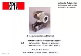
Chapter 5 : Control Systems and Their Components (Instrumentation) Professor Shi-Shang Jang Department of Chemical Engineering National Tsing-Hua University Hsinchu, Taiwan March, 2013
Overview • Need of Instrumentation. • Signals and Signal Levels. • Sensing Element. • What are Final Control Elements? • Characteristics of some transducers and transmitters. • Transmission Signals and representation. • Accuracy of Instrumentation. • What are Transducers and Transmitters?
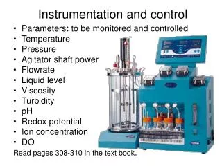
Need of Instrumentation • As already discussed in earlier chapter, we need to measure some parameters to control the process. • Instrumentation is a methodology through which we obtain value of a desired parameter. • Type of instrument to be used is very vital issue and is decided by- • Type of the process. • Instrument’s dead-time & velocity lag. • Accuracy in measurement. • Sampling rate (for digital systems). • Measuring range. • Safety and hazards associated with it.
Transducer Controller Final Control Element Sensor/transmitter An Example- Blending Process (Instrumentation)
3-1 Signals and Signal Levels • Any Data or instruction carrying entity is called a signal. • Signals could be characterized by the nature of information it transport and the medium of Transport. • On the basis of nature of information, the signal could be a continuous signal or a Discrete/DigitalSignal. • On the basis of medium of transport, the signal could be an Electric Signal, Light/Laser Signal, Sound Signal, Radio Signal, Pneumatic Signal etc.
3-1 Signals and Signal Levels cont.. • Signal level is a physical range within which an information is transmitted as a signal. • If the signal is continuous, the signal level are generally continuous. • If the signal is digital, the signal level is a set of discrete values. • Signal levels are an industry standard and may change time to time. • Signal range/level used in industry are- • 1~5 mA • 4~20 mA • 10~50 mA • 0~5 V DC • ± 10 V DC • 3-15 psig
3-1 Sensors/Sensing Element Sensing Elements may be in physical contact with the system and are responsible for determining the parameter. For example- • Temperature-Thermocouples, Filled-bulbs, Resistance (RTD). • Pressure-Bourdon tubes, Strain gauges. • Level- Float position, Difference Pressure, Ultra-sonic level meters. • Flow rate- Orifice plates, Venturi meters, Rotameter. • Composition- Gas chromograph (GC), pH meter, Conductivity, IR absorption, UV absorption.
Sensors/Sensing Element • Characteristics of a linear temperature-current sensing element.
Temp.C Time, sec.
3-2 Final-control Element • After the data for the control variable (CV) and other parameters is processed by the designed controller, signals are sent to Final-control element which manipulates other variables like flow-rate etc. for the system. • Generally, control is done by changing flow rates for the inlet/outlet of material and energy to achieve control and control valves are widely used for it. • Control Valves are of different kinds like- • Pneumatic. • Electro-mechanical. • Manual. • Ball Valve. • Butterfly Valve.
There are generally two type of valve- On/Off Control Valve Proportional 3-2 Control Valve- Final Control Element
3-2 Control Valve- Final Control Element Cont.. • Air to Close(AC) - Valve action to close as the pressure increases. • Air to Open(AO) - Valve action to open as the pressure increases as the previous figure. • The selection of AC or AO control valve is based on the consideration of the emergent need, for instance, the emergent shut down. • A transducer is needed to convert the electronic signal to the pneumatic signal and thus finally controlling the flow rate.
Control Valve- Final Control Element Cont.. Sizing For all valves, the liquid flow rate going through is following the equation below: (5-1) where, F=flow rate;gal/min. P=Pressure drop;psi. Gf =specific gravity of the fluid. Cv =Size, choose the valve size such that at normal operation, the valve is nearly half opened, i.e. vp=0.60.7 vp is the fractional area of the valve that allows the fluid going through, if vp=1, then all area is available (valve fully open), if vp=0, the valve is fully closed.
The graph shows the flow-rate as the function of opening of the valve. Control Valve- Final Control Element Cont.. Valve Characteristics
Control Valve- Final Control Element Cont.. • Valve Characteristics • In most practical cases, equal percentages valves are selected to make sure that the flow rate through the control valve is proportional to the signal vp by choosing correct values of . • This is due to the friction of the fluid through the pipe lines, and in most cases this is non-negligible. pL=kLGf f2 (5-2)
Control Valve- Final Control Element Cont.. Example • Figure 5-2.3 shows a process for transferring an oil from a strage tank to a separation tower. Nominal oil flow is 700 gpm, friction pressure drop is 6 psi, available pressure drop for the control valve is 5 psi.
linear Flow, f Equal percentage vp Control Valve- Final Control Element Cont.. Example Matlab code: >> alpha=50; vp=linspace(0,1); for i=1:100 f(i)=640*alpha^(vp(i)-1)/(sqrt(1+13e-6*(640*alpha^(vp(i)-1))^2))*sqrt(11/0.94); f1(i)=640*vp(i)/(sqrt(1+13e-6*(640*vp(i))^2))*sqrt(11/0.94); end >> plot(vp,f1,vp,f)
Control Valve- Final Control Element Cont.. Transfer Function
What are Transducer and Transmitter? • Transducer is a device which convert one type of signals into another. In other worlds, it may convert one form of energy to another form. • Eg 1: A Digital thermometer’s Transducer convert thermal energy into equivalent electrical signals. • A typical Transducer consist of a sensing element combined with a driving element (transmitter). • Transducers for process control measurements convert the magnitude of a process variable (e.g., flow rate, pressure, temperature, level, or concentration) into a signal that can be sent directly to the controller.
What are Transducer and Transmitter? Cont.. • Transducer is a device which convert one type of signals into another. In other worlds, it may convert one form of energy to another form. • A transmitter is usually required to convert sensor output compatible with the controller input and to drive the transmission lines connecting the two. • Pneumatic (air pressure) signals were used extensively up till 1960s but currently Digital instrumentation is widely used.
Transducer Controller Final Control Element Sensor/transmitter An Example- Blending Process (Instrumentation)
Block Diagram Assume m is small
3-3. Conventional Feedback Controllers - Proportional Controllers R(t) =error=R(t)-C(t) • Kcis called controller gain
3-3 Conventional Feedback Controllers -Proportional Controllers Cont.. control valve saturation 100 Kc=100/50=2 control valve saturation Proportional Band= PB=50/100=50% PB=100/Kc 0 50 Kc<0: Direct Acting Control p increases with y increases Kc>0: Reverse Acting Control p decreases with y increases
Conventional Feedback Controllers • Proportional-Integral Controllers
Conventional Feedback Controllers • Proportional-Integral Controllers Cont.. • The integral actions contribute positive or negative as the signs appeared shown above. However further build up of integral term becomes quite large and the controller is saturated is referred to as reset windup.
Conventional Feedback Controllers • Proportional-Integral Controllers Cont.. • Reset windup occurs when a PI or PID controller encounters a sustained error. In this situation, a physical limitation prevents the controller from reducing the error signal to zero. • It is undesirable to have integral term continue to build up after the controller output saturates. • Commercial controllers available provides anti-reset windup.
Conventional Feedback Controllers • Proportional-Integral-Derivative Controllers
Conventional Feedback Controllers • Proportional-Integral-Derivative Controllers Cont.. • The direct implementation of the derivative term of a PID controller is basically undesirable due to: • Noisy signal is normally received. The derivatives of these signals are meaningless. • The derivative element is physically unrealizable.
No control P-control Response PID-control PI-control time 3-3 Typical Responses of Feedback Control Systems - Continued
No control Kc=1 Response Kc=2 Kc=5 time 3-3 Typical Responses of Feedback Control Systems - Continued
3-4 Process Control Applications • Applications of process control are mostly in the areas of: • Flow rate control • Level control • Air pressure control • Temperature control • Composition control
Flow rate control Applications: inlet flow control, outlet flow control of processes, reflux flow rate, pipeline flow rate,…,etc. Implementation Remarks: (i) Due to the effect of turbulence and pressure fluctuation, the measurement is noisy. (ii) no offset is allowed in flow rate control – integral action is necessary. (iii) flow rate process is fast – no need for derivative actions. Conclusion: PI control is needed with low gain and I10-20 seconds 3-4 Process Control Applications- continued
Liquid level control: Applications: reactor volume control, buffer tank level control, reboiler level control accumulator level control, steam generator level control, …,etc. Implementation: 3-4 Process Control Applications- continued
3-4 Process Control Applications- continued • Remarks: • (i) the level process is basically noisy – fluctuation of the liquid level – low controller gain • (ii) in case of important levels such as reboiler level, accumulator, integral action is needed, • (iii) the level processes are basically a first order system. • Conclusions: The tank level control is basically loose, for instance, to maintain the tank is not completely empty at low inlet flow rate and to maintain tank is not full at high inlet flow rate. Thus, a low gain P controller is frequently implemented. However, in case of important level system such as reboiler level, accumulator, PI controllers should be used. • Other tips: If the outlet of the tank is very important for example, the flow rate to the reactor. Then, the level controller should not influence the flow rate. The controller gain of the P- controller should be tuned to very low.
3-4 Process Control Applications- continued • Air pressure control • Applications: Gas storage tank, air phase reactors. • Remarks: • (i) vapor pressure control is not this case, it should be considered as temperature control in the next slide, • (ii) Gas pressure system is fast – no derivative action is needed, • (iii) the measurement is not noisy. • Conclusions: Use high gain P-only controllers.
3-4 Process Control Applications- continued • Temperature Control • Applications: reactor temperature control, heat exchanger temperature control, temperature control of pre-heaters, vapor pressure control,…,etc. • Manipulated variables: cooling water flow rate, steam flow rate. • Remarks: • (i) the quality of sensor is crucial for this type of control, for instance, sensor noise and time lag will influence the control quality, • (ii) the system is quite slow (heat transfer mechanism), derivative action is needed, • (iii) off set of the temperature is not allowed – integral action is needed, • (iv) there exists an inherent upper bound of the controller gain, process stability is an issue. • Conclusion: A typical PID control situation.
3-4 Process Control Applications- continued • Composition control • Applications: pH control, reactor composition control, distillation composition control, …,etc. • Remarks: • (i) in some cases, the measurements are noisy with time lag (e.g. GC) makes the control very difficult, • (ii) the process is typically slow – derivative action, • (iii) no offset is allowed – integral action. • Conclusion: PID control situation, PI may be implemented in some cases, controller settings are case by case.
3-5 Summary • Instrumentation is a part of the manufacturing process. • The sensors and transmitters are introduced • The sizing and characteristics of control valves are essential for instrumentations • The conventional controllers are derived and analyzed • The applications of the controllers are introduced
Homework • Text p192 • 5-3, 5-5, 5-10, 5-16, 5-18