Download
1 / 13
130 likes | 226 Views
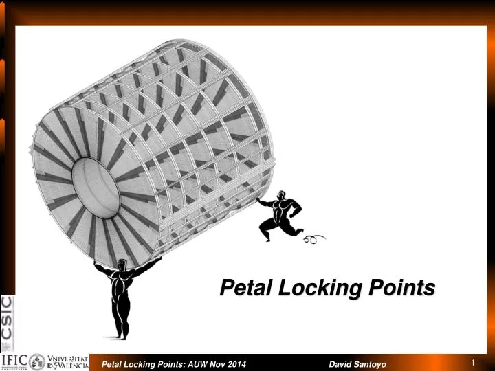
Petal Locking Points. Latest considerations – EC design. EC stiffening disk is located between d6 and d7. BH mechanically decoupled from EC at final position Length of rails and inner cylinder reduced down to disk 7. service modules still extend beyond the BH. Service tray x16.

E N D
Latest considerations – EC design EC stiffening disk is located between d6 and d7 BH mechanically decoupled from EC at final position Length of rails and inner cylinder reduced down to disk 7. service modules still extend beyond the BH
Service tray x16 We loose some space to insert petals between disk 7 and 6 due to stiffening disk. Petals have to be inserted inclined w.r.t. discs since there is not enough RΦ clearance.
Blades 0.18mm thick XN50/RS3 CF facing HC Korex-5/32-2.4 (orStructuralfoam) Petalinsertion guide 1mm thick‘T’ beam CF T300/RS3 • In this model blades play an important structural role. They provide • Quasi-kinematic locking points for the petal and • the required stiffness while allowing to • reduce the Z distance between petals in a disk and cope with the required hermeticity for low momentum tracks and • They are very low density structures (can be made even lighter)
Lockingpoints (noseside) A peek through screw or a dowel pin. (R, Z and Φ constrains) A rotating flap (Z constrain)
Locking points (opposite to nose) If petals must be inserted in angle the local supports should be adapted for that constrain Preliminarydesign to insertpetals in angle
Lockingpoints (oppositetonose) 0.18mm thick XN50/RS3 CF facing HC Korex-5/32-2.4 (orStructuralfoam) Insertion guide Constrains Z and Φ
8 servicetrays ? Recent developments from NIKHEF show that cooling 2 petals in series would be more efficient for the given pipe diameter. https://indico.cern.ch/event/306927/session/0/contribution/23/material/slides/ We could reduce the number of module services by a factor 2.See “common mechanics session”. Byremovingeverysecondservice module, thespaceforpetalinsertionisincreased Petalsconnected in series onbothsides of theservicetray
Service tray x8 Space available to insert petals increases Petals can be inserted parallel to disk plane May allow for new insertion methods
EC FiniteElementModel Update to FEA results shown in https://indico.cern.ch/event/306927/session/10/contribution/92/material/slides/
FEA global structure: adding Si modules • Si wafers • 0.3 mm • 1.31 g/cc • 7 GPa • Thermalglue • 0.2 mm • 2.34 g/cc • 112.4 GPa Siliconsensorsadded to thepetals to checkouthowmuchtheyaffect to the EC structurebehaviour Petal local supportsbeingstudied
Summary • Still too “conceptual” • Seems to work on the simulations • We need to find proper implementations of the locking mechanisms that do not hinder petal insertion and removal • Shall we insert by • sliding along blade or • (if space allows) parallel to disk or • By first inner radius and then upper radius ? • Blade’s C-channel opposite to nose, constrain effectively in z and Φ • “Nose” fixation and blade’s C-channels constrain R, Z and Φ • Is the petal properly fixed in Z with the nose fixation and the flap? We may want to add some extra fixation • Is it petal insertion “friendly” ? Need to exercise and characterize with Endcap mock-up