Download

1 / 37
370 likes | 480 Views
The new high noise immunity range S1-554 and S1-1054 5 and 10kV diagnostic insulation testers. The latest addition to the all new MIT and S1 range of instruments. S1-554 & S1-1054 Diagnostic Instruments. Unique High Noise Rejection. What’s in a name?. S1-554 5 kV max test voltage (DC)

E N D
The new high noise immunity range S1-554 and S1-1054 5 and 10kV diagnostic insulation testers The latest addition to the all new MIT and S1 range of instruments
S1-554 & S1-1054 Diagnostic Instruments Unique High Noise Rejection
What’s in a name? • S1-554 • 5kV max test voltage (DC) • 5mA test current output • 4mA Noise rejection • S1-1054 • 10kV max test voltage (DC) • 5mA test current output • 4mA Noise rejection
Designed for the harshest conditions • High noise immunity • High test current • High accuracy • High measurement range • High voltage option • High guard terminal performance • High impact resistant case • IP65 sealed case • Mains or battery operation • Lid mounted test lead bag So what does that really mean to you?
High Noise Immunity • Noise? • Induced current from adjacent powered up equipment • Causes variation in readings • In high noise locations measurement often impossible • The solution? • S1-554 and S1-1054 incorporates latest filter techniques • Both Hardware and Firmware filtering • Hardware for fast moving variations • Firmware filtering for slower variations • User selectable Firmware time constants (10, 30 & 100 seconds)
High Noise Immunity? • EMC issue • Noise immunity needs to take into account all issues not just current induced into the test piece • Other EMC phenomena such as RF susceptibility, transients, etc. can effect measurements too • Hence full compliance to EN61326-1:1998 for use in heavy industrial environments
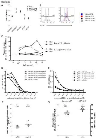
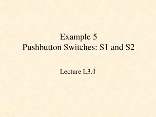
High Test Current? • S1-554 and S1-1054 equipped with market leading 5mA output • Why? • To charge capacitance on long cables quickly – saving valuable time • Capacitor charge time: < 3seconds per µF at 5mA • High output means higher voltage applied to lower insulation values showing it’s true condition
5000 V 5 kV 4 kV 3 kV Voltage 2500 V 2 kV 1000 V 1 kV 0 0 1 G 10 G 1 M 100 k 100 G 10 M 100 M Resistance Result of lower output competitor
5000 V 5 kV 4 kV Voltage 3 kV 2500 V 2 kV 1000 V 1 kV 500 V 0 0 1 G 10 G 100 M 1 M 100 k 10 M 100 G Resistance Result of high output
High Accuracy? • S1-554 and S1-1054 give accurate and repeatable results • Typically ±5% • Why? • Meaningful diagnostic insulation testing totally relies upon trending results • Inaccurate reading mean inaccurate trending
High Measurement range? • S1-554 and S1-1054 have market leading measurement ranges • S1-554 = 15T • S1-1054 = 35T • Why? • You cannot analyse or trend infinity readings Start of insulation degradation Readings taken at >1T 500G range limit Could be months Time (months) Degradation noticed much later with 500G range
High Voltage Option? • S1-1054 has up to 10kV output • Industry standard is 5kV • Why? • Higher test voltage produces higher current though insulation hence higher test range • IEEE43-2000 “Recommended practice for testing insulation resistance of rotating machines” recommends testing >12kV rated winding with up to 10kV • Future proofs instrument against future developments in insulation technology • 10kV remains at a none destructive level, the aim is for enough current to flow to be able to analyse it’s condition not to stress it
High guard terminal performance? • The S1-554 and S1-1054 gives only 2% error when guarding 500k leakage across a 100M load • The guard terminal removes the effect of surface leakage due to dirt and moisture • Surface leakage gives a lower result than normal • Why? • Poor guard terminal performance means readings taken after removing the effects if surface leakage will be incorrect, resulting in incorrect analysis of insulation condition
High quality Case? • The S1-554 and S1-1054 is built to take the knocks and is IP65 rated with lid closed • Why? • These instrument can have a hard life, thrown into vans, used outside, accidentally dropped etc. • Instruments need to be built for the job to prevent unwelcome time in the repair workshop • You rely on your instrument to be ready when you need it
Mains or battery operation? • The S1-554 and S1-1054 can operate from both rechargeable battery or a mains supply • Mains voltage range 85V – 260V, 50/60Hz • Battery life – 6 hours continuous testing at 5kV, 4 hrs at 10kV • Why? • Extremely high battery life is only any good if you remember to charge it • Saves time waiting to charge when long term testing is required
Lid mounted test lead bag? • Ever gone to perform some testing only to find the test leads are missing? • Some sub-standard products use separate lead bags
Other important features • Capacitance measurement • Voltage at terminals measurement • On display during test • Automatic Tests • Polarisation Index (PI) • Dielectric Absorption Ratio (DAR) • Step Voltage • Dielectric Discharge (DD) • Timer range: Up to 99 minutes and 59 seconds • T1, T2 and main timer T • Allows you to define two measurement times and an overall duration for the test.
Other important features • Large analogue and digital backlit display • Analogue to show variation • Digital to give precise value • Data stored in memory: Voltage, test time, leakage current, resistance, PI, DAR, DD, capacitance and time constant • 32k = 56 tests each of 45min duration • Real time output: Serial, once a second, voltage, current and resistance • Interface: RS232 (9 pin connector) and USB
Software supplied • Megger Download Manager • Download Manager in many languages • Includes ability to draw graphs of test results quickly and easily from standard output .csv files • Also easily imported to Excel if required • Supplied on CD with the instruments and also downloadable from Megger web site
Standard Test Leads Supplied • Existing un-insulated small clip 3 metre leads • 8101-181 • 10kV basic insulation, 5kV double insulation • Designed to protect user from instrument output NOTlive busbars and for larger size connections • S1-1054 only
Standard Test Leads Supplied • 6kV basic insulation, 3kV double insulation • Again designed to protect user from instrument output up to 3kV and allow access in more constrained environments
Test lead options • 1kV double insulated (Accessory) • Modified to allow connection to MIT 5 & 10kV • Rated at 1kV CAT III(CATII with croc clips fitted)only • Allows customers to test control circuits up to 1000V, for example around high voltage switchgear
Power On/Off button • The instrument will only turn on if this button is pressed, held and then released when the display responds. • Too short or too long a press will not work • This is a safety feature to prevent the instrument being inadvertently turned on. • The instrument is turned off either by pressing the button again, or if the instrument is running on the battery, by timing out after 10 minutes of inactivity.
Test voltage setting • Using the voltage up/down keys you can select either 250V, 2.5kV, 5kV or 10kV (S1-1054) • Holding down the ‘Fn’ button whilst operating the up/down keys allows voltages to be selected between 50v and the instruments maximum voltage in increments of: • 50V to 1kV in 10V steps • 1kV to 5kV in 25V steps (S1-554) • 1kV to 10kV in 25V steps (S1-1054) Voltage up/down keys Function key
Test start / stop button • The test will only start if the ‘test’ button is pressed, held and released when the red HV warning LED lights. • Too short or too long a press will not work • This is a safety feature to prevent a test being started accidentally. • Note: if a voltage >50V is detected on the terminals the red HV warning LED will flash as a warning. >160V will disable testing. • Pressing the ‘test’ button during testing stops the test.
/I button • This button toggles both the main digital display between and I, and the secondary display across the bottom • Secondary displays depends on test mode selected (IR, SV, PI, DD or DAR), and whether timers T1 and T2 are set.
Fn button • The function button when pressed allows other keys to perform another functions too • See table below
Mode button • Pressing this button cycles through the test modes • Insulation resistance ‘IR’, Polarization Index ‘PI’, Step voltage ‘SV’, and Dielectric discharge ‘DD’ tests • IR can operate in either ‘burn’ or ‘breakdown mode’ using ‘Fn’ + ‘mode’ keys in IR mode
Timer and buttons • The main timer can be set up to 99min 59sec • Holding down ‘Fn’ button whilst pressing one of these buttons selects either T main, T1 or T2 timers • To set timers release ‘Fn’ button first • Minimum timer setting is 15 sec for test voltages >1kV, and 30 sec <1kV
Record button • The button activates or deactivates data recording • Recording can only be activated before starting a test • When enabled the data recording symbol flashes • Data is stored in a solid state 32k memory (e.g. • Results are stored at 15, 30, 45 and 60 seconds, then at 1 minute intervals. After 10mins at 5 min interval until test terminates Record symbol
Battery bar graph • The battery status in monitored continuously • Charge remaining is indicated in five levels giving the operator a real indication of battery life Battery fully charged Battery 75% charged Battery 50% charged Battery 25% charged Battery may fail at any time not enough charge to perform test
Secondary display This part of the display shows the results of ‘time resistance’ method tests.
Using the filters • Hardware filter • May be switched off, but not during a test • Press and hold ‘Fn’ button while repeatedly pressing the /I button to select either ‘FIL ON’ or ‘FIL OFF’ • Firmware filter • ‘FIL ON’ must be selected before test is started • Press and hold ‘Fn’ button while repeatedly pressing the /I button to select firmware filter options during test. • Filter time constants may be set to 10, 30, or 100 seconds
Summary • S1-554 and S1-1054 represents the ultimate in diagnostic insulation testing performance in all environments • Key Features • High noise immunity • High test current • High accuracy • High Measurement ranges • All backed up with full technical and after sales support • Further information available on www.megger.com


![[S1]](https://cdn2.slideserve.com/4310044/slide1-dt.jpg)