Download
1 / 23
230 likes | 247 Views
This method by Ray Jorgensen and David Lempia details how to describe the problem space, originating from customer requirements by identifying stakeholder needs, adding necessity, and using SysML concepts. The approach involves creating operational concepts, conducting use case analysis, and building scenarios through activity diagrams.

E N D
Practical SysML Applications: A Method to Describe the Problem Space Ray Jorgensen David Lempia
Problem Space Abstraction Views
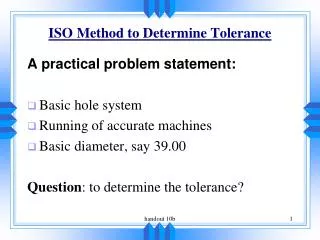
Originating Customer Requirements • Answer the questions: • What is the problem? • What are the users doing? • What are the objects in the real world? • Work from the user requirements inward • Ends with requirements review • Vocabulary consistent between domain model, requirements, and use cases
3) Identify Stakeholder Needs Stakeholder needs 1) Identify stakeholders 2) Describe stakeholders Roles: Describe the role the stakeholder plays. There may be more than one role each stakeholder operates in. Authority: Describe the authority of the stakeholder in each of their roles. Knowledge: Describe the level of knowledge the stakeholder has. 4) Add need necessity & rational
Source Requirements • Study in the application of SysML concepts to avionics development and TCP workflow • INU Update: • 3.2.1.8 Weather Radar • The existing weather radar system SHALL be integrated into the flight deck and provide control for skin-paint, ground mapping, and INU update functions to pilot, co-pilot, and navigator stations.
Capture Architectural Context • Show actors and association with system of interest • Purely “black box” perspectives
Operational Concepts • Start with functional requirements and stakeholder needs • Create a satisfy trace to each activity/action generated from a functional requirement as the diagram is built • Re-use actors and external systems from the stakeholders and architecture context packages • If you discover a new actor or system, add it to the stakeholder/architecture context also
Use Case Diagram Actor Dependency (extend/include) Use Case Stereotype Association Composite (Use Case Diagram) (Activity Diagram) Block – My system or other systems
Conduct Use Case Analysis • Identify prospective Use Case: “verb-noun” convention • Primary actor identification
Characterize Use Case • Purpose, Goal, or Objective • Trigger Stimulus • Preconditions • Post Conditions
Define Scenario • Add activities of primary actor
Define Scenario • Add Activities of system of interest and other supporting actors • Maintain purely “black box” perspective
Organize Model Elements • Activity Diagrams (Scenarios) under Use Case elements • Make Use Case “composite” – double click opens scenario
Add Exceptions and Alternate Courses • Examine each “happy day” step (activity) • What can go wrong? • What else might the actor do? • Does the step itself require further elaboration (extension)? • Simple dependency relationship from activity to use case
Use Case Extensions • Add: • Alternate Courses • Exceptions Cases • Extensions • Maintain singular focus • One use case is primary focus of Use Case Diagram
Elaborate Each Extension • Activity diagram (scenario) for each AC or EX • May be variant of original use case scenario
Scenario Diagrams • Generally, use Activity Diagrams to express unique scenarios • However, if alternate course or exception is “simple”, consider “Notes” narrative • Use Case Analysis generates future opportunities – capture them!
Repeat Use Case Process • 1) Use Case identification • 2) Scenario definition – primary actor • 3) Scenario definition – system of interest, seconday actors • 4) Consider alternate courses/ exceptions/ extensions
Add Object Flows • Add object flow for each interaction • Two activity diagrams: • Sequence flow of scenario • Object flow of scenario • However: • Consider transaction “visibility” between actors (swimlanes) • Consider activity hierarchy (functional decomposition)
Further Consideration • When to use Actions vs. Activities • Object Flows vs. Object Nodes • Extended scenarios – from “black box” problem space into “white box” solution space • Functional Allocation • “Allocate” relationship vs. Tagged Value “Relationship” • Inheritance through instantiation • Interface Allocation • Object Flow/ Data Item allocation to Software Data Stream messages • Object Flow allocation to Human Machine Interface