Download

1 / 45
1.39k likes | 3.8k Views
Biopotential Electrodes. Electrode – Electrolyte Interface. Electrode Electrolyte (neutral charge). C+, A- in solution. C. Current flow. C. C+. e-. C. A-. C+. e-. A-. C+ : Cation A- : Anion e- : electron. Fairly common electrode materials: Pt, Carbon, …, Au, Ag,…

E N D
Electrode – Electrolyte Interface ElectrodeElectrolyte (neutral charge) C+, A- in solution C Current flow C C+ e- C A- C+ e- A- C+ : Cation A- : Anion e- : electron Fairly common electrode materials: Pt, Carbon, …, Au, Ag,… Electrode metal is use in conjunction with salt, e.g. Ag-AgCl, Pt-Pt black, or polymer coats (e.g. Nafion, to improve selectivity)
Electrode – Electrolyte Interface General Ionic Equations a) b) a) If electrode has same material as cation, then this material gets oxidized and enters the electrolyte as a cation and electrons remain at the electrode and flow in the external circuit. b) If anion can be oxidized at the electrode to form a neutral atom, one or two electrons are given to the electrode. The dominating reaction can be inferred from the following : Current flow from electrode to electrolyte : Oxidation (Loss of e-) Current flow from electrolyte to electrode : Reduction (Gain of e-)
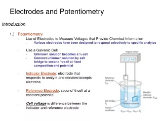
Half Cell Potential A characteristic potential difference established by the electrode and its surrounding electrolyte which depends on the metal, concentration of ions in solution and temperature (and some second order factors) . Half cell potential cannot be measured without a second electrode. The half cell potential of the standard hydrogen electrode has been arbitrarily set to zero. Other half cell potentials are expressed as a potential difference with this electrode. Reason for Half Cell Potential : Charge Separation at Interface Oxidation or reduction reactions at the electrode-electrolyte interface lead to a double-charge layer, similar to that which exists along electrically active biological cell membranes.
Measuring Half Cell Potential Note: Electrode material is metal + salt or polymer selective membrane
Some half cell potentials Standard Hydrogen electrode Note: Ag-AgCl has low junction potential & it is also very stable -> hence used in ECG electrodes!
Polarization If there is a current between the electrode and electrolyte, the observed half cell potential is often altered due to polarization. Note: Polarization and impedance of the electrode are two of the most important electrode properties to consider.
Nernst Equation When two aqueous ionic solutions of different concentration are separated by an ion-selective semi-permeable membrane, an electric potential exists across the membrane. For the general oxidation-reduction reaction Note: interested in ionic activity at the electrode (but note temp dependence The Nernst equation for half cell potential is where E0 : Standard Half Cell Potential E : Half Cell Potential a : Ionic Activity (generally same as concentration) n : Number of valence electrons involved
Polarizable and Non-Polarizable Electrodes Use for recording Perfectly Polarizable Electrodes These are electrodes in which no actual charge crosses the electrode-electrolyte interface when a current is applied. The current across the interface is a displacement current and the electrode behaves like a capacitor. Example : Ag/AgCl Electrode Perfectly Non-Polarizable Electrode These are electrodes where current passes freely across the electrode-electrolyte interface, requiring no energy to make the transition. These electrodes see no overpotentials. Example : Platinum electrode Use for stimulation Example: Ag-AgCl is used in recording while Pt is use in stimulation
Ag/AgCl Electrode Relevant ionic equations Cl2 Governing Nernst Equation Solubility product of AgCl Ag+Cl- • Fabrication of Ag/AgCl electrodes • Electrolytic deposition of AgCl • Sintering process forming pellet electrodes
Equivalent Circuit Cd: capacitance of electrode-eletrolyte interface Rd: resistance of electrode-eletrolyte interface Rs : resistance of electrode lead wire Ecell : cell potential for electrode Corner frequency Rd+Rs Rs Frequency Response
Ese EP Re Ce RP CP Electrode Skin Interface Ehe Alter skin transport (or deliver drugs) by: Pores produced by laser, ultrasound or by iontophoresis Electrode Cd Rd Sweat glands and ducts Rs Gel 100 m Stratum Corneum Epidermis 100 m Dermis and subcutaneous layer Ru Skin impedance for 1cm2 patch: 200kΩ @1Hz 200 Ω @ 1MHz Nerve endings Capillary
Motion Artifact Why When the electrode moves with respect to the electrolyte, the distribution of the double layer of charge on polarizable electrode interface changes. This changes the half cell potential temporarily. What If a pair of electrodes is in an electrolyte and one moves with respect to the other, a potential difference appears across the electrodes known as the motion artifact. This is a source of noise and interference in biopotential measurements Motion artifact is minimal for non-polarizable electrodes
Body Surface Recording Electrodes Electrode metal Electrolyte Think of the construction of electrosurgical electrode And, how does electro-surgery work? • Metal Plate Electrodes (historic) • Suction Electrodes • (historic interest) • Floating Electrodes • Flexible Electrodes
Commonly Used Biopotential Electrodes Metal plate electrodes • Large surface: Ancient, therefore still used, ECG • Metal disk with stainless steel; platinum or gold coated • EMG, EEG • smaller diameters • motion artifacts • Disposable foam-pad: Cheap! (a) Metal-plate electrode used for application to limbs. (b) Metal-disk electrode applied with surgical tape. (c)Disposable foam-pad electrodes, often used with ECG
Commonly Used Biopotential Electrodes • Suction electrodes • No straps or adhesives required • precordial (chest) ECG • can only be used for short periods • Floating electrodes • metal disk is recessed • swimming in the electrolyte gel • not in contact with the skin • reduces motion artifact Suction Electrode
Commonly Used Biopotential Electrodes Metal disk Insulating package Double-sided Adhesive-tape ring Electrolyte gel in recess Reusable (a) (b) External snap Snap coated with Ag-AgCl Gel-coated sponge Disposable Plastic cup Plastic disk Dead cellular material Tack Foam pad Capillary loops Germinating layer (c) Floating Electrodes
Commonly Used Biopotential Electrodes • Flexible electrodes • Body contours are often irregular • Regularly shaped rigid electrodes • may not always work. • Special case : infants • Material : • - Polymer or nylon with silver • - Carbon filled silicon rubber • (Mylar film) (a) Carbon-filled silicone rubber electrode. (b) Flexible thin-film neonatal electrode.(c) Cross-sectional view of the thin-film electrode in (b).
Internal Electrodes Needle and wire electrodes for percutaneous measurement of biopotentials (a) Insulated needle electrode. (b) Coaxial needle electrode. (c) Bipolar coaxial electrode. (d) Fine-wire electrode connected to hypodermic needle, before being inserted. (e) Cross-sectional view of skin and muscle, showing coiled fine-wire electrode in place. The latest: BION – implanted electrode for muscle recording/stimulation Alfred E. Mann Foundation
Fetal ECG Electrodes Electrodes for detecting fetal electrocardiogram during labor, by means of intracutaneous needles (a) Suction electrode. (b) Cross-sectional view of suction electrode in place, showing penetration of probe through epidermis. (c) Helical electrode, which is attached to fetal skin by corkscrew type action.
Insulated leads Contacts Ag/AgCl electrodes Ag/AgCl electrodes Contacts Base (b) Base Insulated leads (a) Tines Exposed tip Base (c) Electrode Arrays Examples of microfabricated electrode arrays. (a) One-dimensional plunge electrode array, (b) Two-dimensional array, and (c) Three-dimensional array
Microelectrodes Why Measure potential difference across cell membrane Requirements • Small enough to be placed into cell • Strong enough to penetrate cell membrane • Typical tip diameter: 0.05 – 10 microns Types • Solid metal -> Tungsten microelectrodes • Supported metal (metal contained within/outside glass needle) • Glass micropipette -> with Ag-AgCl electrode metal Intracellular Extracellular
Metal Microelectrodes C Microns! R Extracellular recording – typically in brain where you are interested in recording the firing of neurons (spikes). Use metal electrode+insulation -> goes to high impedance amplifier…negative capacitance amplifier!
Metal Supported Microelectrodes (a) Metal inside glass (b) Glass inside metal
Ag-AgCl wire+3M KCl has very low junction potential and hence very accurate for dc measurements (e.g. action potential) Glass Micropipette heat pull A glass micropipet electrode filled with an electrolytic solution (a) Section of fine-bore glass capillary. (b) Capillary narrowed through heating and stretching. (c) Final structure of glass-pipet microelectrode. Fill with intracellular fluid or 3M KCl Intracellular recording – typically for recording from cells, such as cardiac myocyte Need high impedance amplifier…negative capacitance amplifier!
Electrical Properties of Microelectrodes Metal Microelectrode Metal microelectrode with tip placed within cell Equivalent circuits Use metal electrode+insulation -> goes to high impedance amplifier…negative capacitance amplifier!
Electrical Properties of Glass Intracellular Microelectrodes Glass Micropipette Microelectrode
Stimulating Electrodes Features – Cannot be modeled as a series resistance and capacitance (there is no single useful model) –The body/electrode has a highly nonlinear response to stimulation – Large currents can cause –Cavitation –Cell damage –Heating Platinum electrodes: Applications: neural stimulation Modern day Pt-Ir and other exotic metal combinations to reduce polarization, improve conductance and long life/biocompatibility Steel electrodes for pacemakers and defibrillators • Types of stimulating electrodes • Pacing • Ablation • Defibrillation
Intraocular Stimulation Electrodes Reference : Lutz Hesse, Thomas Schanze, Marcus Wilms and Marcus Eger, “Implantation of retina stimulation electrodes and recording of electrical stimulation responses in the visual cortex of the cat”, Graefe’s Arch Clin Exp Ophthalmol (2000) 238:840–845
In vivo neural microsystems (FIBE): biocompatibility - variant
Introduction: neural microsystems Instrumentation for neurophysiology Neural Microsystems MEMS - Microsystems Neural microelectrodes
External electrodes Subdural electrodes Micro-electrodes Microsensors Human level – Animal level Tissue slice level – – Cellular level – – Introduction: types of neural microsystems applications In vivo applications In vitro applications
Bonding pads Insulated lead vias SiO2 insulated Au probes Exposed electrodes Silicon probe Si substrate Exposed tips (a) (b) Miniature insulating chamber Channels Silicon chip Hole Lead via Silicon probe Contact metal film Electrode (d) (c) Microelectronic technologyfor Microelectrodes Beam-lead multiple electrode. Multielectrode silicon probe Multiple-chamber electrode Peripheral-nerve electrode Different types of microelectrodes fabricated using microfabrication/MEMS technology
Neural Recording Microelectrodes Reference : http://www.acreo.se/acreo-rd/IMAGES/PUBLICATIONS/PROCEEDINGS/ABSTRACT-KINDLUNDH.PDF
In vivo neural microsystems: 3 examples University of Michigan Smart comb-shape microelectrode arrays for brain stimulation and recording University of Illinois at Urbana-Champaign High-density comb-shape metal microelectrode arrays for recording Fraunhofer Institute of Biomedical (FIBE) Engineering Retina implant
Multi-electrode Neural Recording Reference : http://www.cyberkineticsinc.com/technology.htm Reference : http://www.nottingham.ac.uk/neuronal-networks/mmep.htm
Left: Schematic of the 16-electrode sensor array. Right: Close-up of a single site. The underlying metal is Au and appears reddish under the photoresist. The dark layer is C (300µm-x-300µm) Nitric Oxide Sensor • Developed at Dr.Thakor’s Lab, BME, JHU • Electrochemical detection of NO
A E B F C G D H Cartoon of the fabrication sequence for the NO sensor array A) Bare 4” Si wafer B) 5µm of photoresist was spin-coated on to the surface, followed by a pre-bake for 1min at 90°C. C) The samples were then exposed through a mask for 16s using UV light at 365nm and an intensity of 15mW/cm2. D) Patterned photoresist after development. E) 20nm of Ti, 150nm of Au and 50nm of C were evaporated on. F) The metal on the unexposed areas was removed by incubation in an acetone bath. G)A 2nd layer of photoresist, which serves as the insulation layer, was spun on and patterned. H) The windows in the second layer also defined the microelectrode sites.