Download
1 / 10
100 likes | 116 Views
Learn about the binary number system, digital logic devices, powers of 2, and logic operations. Explore how electronic circuits in binary form handle data and the basics of digital logic.

E N D
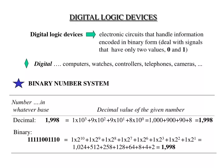
BINARY NUMBER SYSTEM Digital logic devices Number ….in whatever base Decimal value of the given number ___________________________________________________________________________________________________________________________________________________________________ Decimal: 1,998 = 1x10³ +9x10² +9x101 +8x100 =1,000+900+90+8 =1,998 Binary: 11111001110 = 1x210 +1x29 +1x28 +1x27 +1x26 +1x23 +1x22 +1x21 = 1,024+512+258+128+64+8+4+2 = 1,998 DIGITAL LOGIC DEVICES electronic circuits that handle information encoded in binary form (deal with signals that have only two values, 0 and 1) Digital …. computers, watches, controllers, telephones, cameras, ...
________________________________________________________________________________________________________________________________________________________________________________________________________________________________________________________________________________________________________________________________________ N 2N Comments _____________________________________________________________________________________________________________________________________________________________________ 0 1 1 2 2 4 3 8 4 16 5 32 6 64 7 128 8 256 9 512 10 1,024 “Kilo”as 210 is the closest power of 2 to 1,000 (decimal) 11 2,048 ………………………………………………………..... 15 32,768 215 Hz often used as clock crystal frequency in digital watches ……………………………………………………..... 20 1,048,576 “Mega” as 220 is the closest power of 2 to 1,000,000 (decimal) …………………………………………………... 30 1,073,741,824 “Giga” as 230 is the closest power of 2 to 1,000,000,000(decimal) ____________________________________________________________________________________________________________________________________________________________________ Powers of 2
__________________________________________________________________________________________________________________________ N <0 2N ____________________________________________________________ -1 2-1 = 0.5 -2 2-2 = 0.25 -3 2-3 = 0.125 -4 2-4 = 0.0625 -5 2-5 = 0.03125 -6 2-6 = 0.015625 -7 2-7 = 0.0078125 -8 2-8 = 0.00390625 -9 2-9 = 0.001953125 -10 2-10 = 0.0009765625 … _____________________________________________________________ Binary numbers less than 1 Binary Decimal value ----------------------------------------------------------------------------------------------------------------- 0.101101 Negative Powers of 2 = 1x2-1 +1x2-3 + 1x2-4 + 1x2-6 = 0.703125
HEXADECIMAL ---------------------------------------------------------------------------------------------------- Binary Decimal Hexadecimal ---------------------------------------------------------------------------------------------------- 0000 0 0 0001 1 1 0010 2 2 0011 3 3 0100 4 4 0101 5 5 0110 6 6 0111 7 7 1000 8 8 1001 9 9 1010 10 A 1011 11 B 1100 12 C 1101 13 D 1110 14 E 1111 15 F ---------------------------------------------------------------------------------------------------- Binary: 11111001110 7 12 14 <== Decimal = 7x162 +12x161 +14x160 = 1998 1111100 1110 Hexadecimal: 7CE
LOGIC OPERATIONS AND TRUTH TABLES Binary logic dealing with “true” and “false” comes in handy to describe the behaviour of these circuits: 0 is usually associated with “false” and 1 with “true.” Quite complex digital logic circuits (e.g. entire computers) can be built using a few types of basic circuits called gates, each performing a single elementary logic operation : NOT, AND, OR, NAND, NOR, etc.. Boole’s binary algebra is used as a formal (mathematical) tool to describe and design complex binary logic circuits. More info on the digital logic big names Boole, Turing, Shannon is available in the Annex F of the textbook. Digital logic circuits handle data encoded in binary form, i.e. signals that have only two values, 0 and 1.
GATES A A ______________________ 0 1 1 0 A F =A . B B A B A . B _____________________________________ 0 0 0 0 1 0 1 0 0 1 1 1 _____________________________________ F =A A A B A + B _____________________________________ 0 0 0 0 1 1 1 0 1 1 1 1 _____________________________________ A F = A + B B AND NOT OR
… more GATES A B A . B _____________________________________ 0 0 1 0 1 1 1 0 1 1 1 0 _____________________________________ A F =A . B B A B A +B _____________________________________ 0 0 1 0 1 0 1 0 0 1 1 0 _____________________________________ A F = A + B B NAND NOR
… and more GATES A B A B _____________________________________ 0 0 0 0 1 1 1 0 1 1 1 0 _____________________________________ A F = A B F = A B B A B A B _____________________________________ 0 0 1 0 1 0 1 0 0 1 1 1 _____________________________________ A B XOR EQU or XNOR
GATES … with more inputs A+B+C ___________________ 0 1 1 1 1 1 1 1 ___________________ A.B.C ___________________ 1 1 1 1 1 1 1 0 ___________________ A+B+C ___________________ 1 0 0 0 0 0 0 0 ___________________ A B C A. B.C ______________________________________________ 0 0 0 0 0 0 1 0 0 1 0 0 0 1 1 0 1 0 0 0 1 0 1 0 1 1 0 0 1 1 1 1 _______________________________________________ F =A.B.C A A A A F = A+B+C F = A+B+C B B B B F =A.B.C C C C C EXAMPLES OF GATES WITH THREE INPUTS AND OR NAND NOR
Logic Gate Array that Produces an Arbitrarily Chosen Output A B C A . B . C + A . B . C + A . B . C + A . B . C A B C F ________________________________________ 0 0 0 0 0 0 1 0 0 1 0 1 0 1 1 1 1 0 0 0 1 0 1 1 1 1 0 0 1 1 1 1 _________________________________________ A . B . C A . B . C F A . B . C A . B . C A B C A B C F =