Download
1 / 24
250 likes | 551 Views
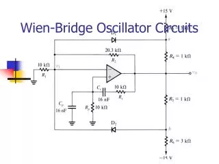
Oscillator Circuits. Outline. Oscillators Inverter-Based Oscillator Introduction of Phase Noise Simulation LC-Tank Based Oscillator Laplace Analysis Circuit Implementation Quality Factor Analysis. Inverter-Based Oscillator. Delay Per Stage of the Inverter. (395 ps ). (273 pS ).

E N D
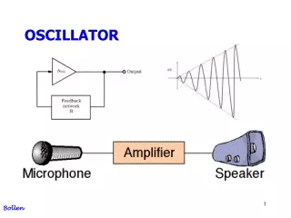
Outline • Oscillators • Inverter-Based Oscillator • Introduction of Phase Noise Simulation • LC-Tank Based Oscillator • Laplace Analysis • Circuit Implementation • Quality Factor Analysis
Delay Per Stage of the Inverter (395 ps) (273 pS) Period: 395-273=122 pS, Delay per stage (TD): 234-214=20 pS. Period is 2NTD
Oscillation Frequency Calculation • fosc=2.14 GHz • Tosc=467 pS=2NTD • TD=20 pS • N=Tosc/(2TD)=467 pS/(2 20)=11.68 • N must be odd. • Choose N as 11.
11 Stage Oscillator Period: 1.501 nS-1.052 nS=0.449 nS, Freq=2.227 GHz
LC Tank Oscillator • Resonant Frequency: 2.14 GHz • L=1 nH • C=5.53 pF (Adjustable)
Transient Simulation (Steady state after 10 nS) Frequency: 1.941GHz
Reduce the Value of Capacitor (2.16 GHz)
Quality Factor of 10 for the inductor Oscillation dies out since gtankis greater than gm of the transistor.
Rind=100 mΩ This is the maximum parasitic resistance we can have without destroying the oscillation.
Phase Noise with Rind=100 mΩ Even a little series resistance at unreasonably high Q (130) can degrade phase noise quickly.