Download
1 / 25
270 likes | 417 Views
OSCILLATOR. Bollen. What is oscillation Analog oscillation WIEN bridge oscillator High pass and low pass combined Relaxatin oscillator RC circuit 15k and 10 nF Voltage diviver 15k and 15k Comparator Signals and output Charge Discharge. Frequency = 1 / total time Variationa

E N D
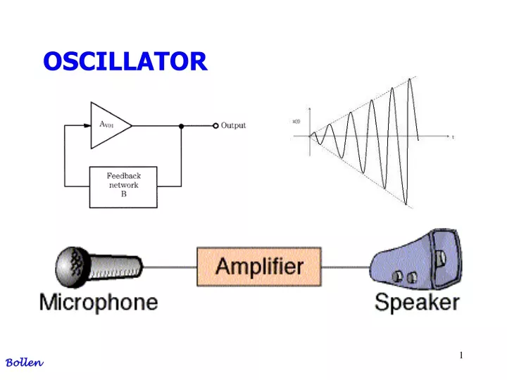
OSCILLATOR Bollen
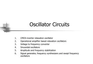
What is oscillation Analog oscillation WIEN bridge oscillator High pass and low pass combined Relaxatin oscillator RC circuit 15k and 10 nF Voltage diviver 15k and 15k Comparator Signals and output Charge Discharge Frequency = 1 / total time Variationa Summary AGENDA Bollen
What is oscillation Circuit powered by Vcc and Vee No input signal, only output signal Wienbridge Oscillator; output signal is sine wave (used for making radio frequencies) Relaxation Oscillatoer; output signal is a “digital” block signal (used for clock or count circuits) Bollen
Barkhausen criterium: Loopgain = 1 Total phase = 0 or 360 What is analog oscillationWIEN bridge oscillator Bollen
Oscillator for High frequency Sine signals It uses 2 filters; High pass and low pass For one frequency the phase = 0 degrees !!!! WIEN bridge oscillator Bollen
WIEN bridge oscillator Barkhausen criterium: Loopgain = 1 Total phase = 0 or 360 Bollen
WIEN bridge oscillator After “short” mathematics; Bollen
WIEN bridge oscillator Bollen
WIEN bridge oscillator Bollen
WIEN bridge oscillator For phase = o degrees; imaginair part = 0 Bollen
WIEN bridge oscillator For R1 = R2 = R And C1 = C2 = C At oscillation IM = 0 Au = 1/3 so amplificaton should be +3 Rf = 2 Rs Bollen
WIEN bridge oscillator Bollen
RC-circuit 15k and 10nF; charge / discharge Voltage divider 15k and 15k; high treshold / low treshold Comparator Output: block Vcc / Vee What is “digital” oscillationRelaxation oscillator Bollen
Vin = Vcc = +12 for charge And = Vee = -12 for discharge RC-circuit 15k and 10nF Bollen
Vin = +12 volt = opamp output high or Vin = - 12 volt = opamp output low V treshold up = +6 V for +12 opamp output V treshold low = -6 V for – 12 opamp output Voltage divider 15k and 15k Bollen
Inverting input; Uc, capacitor voltage Non inverting input; Treshold voltage, high (+6 Volt) or low (-6 volt) Output: Comparator Bollen
Signals and output Blue = output signal (+12 Volt or – 12 Volt) Green = treshold signal (+6 Volt of – 6 Volt) Red = capacitor signal Bollen
Calculate 2nd charge track! Why? Charge R = 15 k C = 10 nF Vfinal = +12 V Vinitial = -6 V Switch at Vc = +6 Volt Bollen
Discharge R = 15 k C = 10 nF Vfinal = -12 V Vinitial = +6 V Switch at Vc = -6 Volt Bollen
Frequency = 1 / (total time) Bollen
By using diodes; Charge time and Discharge time are different !! Treshold remains the same So … duty cylce is controlable; up time ≠ down time Variations 1 Bollen
Frequency control by changing the voltage divider Vtreshold up Vtreshold low Variations 2 Bollen
Analyse yourself .. .. .. Conclusion? Summary 1 Bollen
Analyse yourself .. .. .. Conclusion? Summary 2 Bollen