Download
1 / 40
400 likes | 542 Views
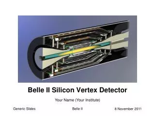
STAR Silicon Vertex Tracker Detector (SVT) Update. Nothing tends so much to the advancement of knowledge as the application of a new instrument - Sir Humphrey Davy (1778-1829). Helen Caines - Yale University. Presentation Overview. SVT Introduction SVT Performance

E N D
STAR Silicon Vertex Tracker Detector (SVT) Update Nothing tends so much to the advancement of knowledge as the application of a new instrument - Sir Humphrey Davy (1778-1829) Helen Caines - Yale University
Presentation Overview • SVT Introduction • SVT Performance • Track-to-Hit Matching • Vertex Reconstruction • Energy Loss • Strange Particle Decays • Summary & Conclusions
The STAR Detector Time Projection Chamber FTPCs (1 +1) Vertex Position Detectors Magnet Coils Silicon Vertex Tracker * TPC Endcap & MWPC ZCal ZCal Endcap Calorimeter Barrel EM Calorimeter Central Trigger Barrel + TOF patch RICH * yr.1 SVT ladder • 1st year, 2nd year,year-by-year until 2003, installation in 2003
SVT Installation Installed for the first time 2001-2 RHIC run
p-p vs Au-Au at √sNN=200 GeV Two very different environments: p-p - Few tracks, primary vertex not well known high luminosity Au-Au – Few 1000 tracks Vertex well located Track/hit merging
SVT Design Each wafer is 6.3 cm x 6.3 cm area 300 mm thick - 0.3%X0 Average radiation length seen by a particle 4.5%X0 incl. fee cards etc. Consists of 216 wafers 3 Barrels Outer radius – 15cm Middle Radius – 10cm Inner radius - 6cm Length - 21cm Inner barrel has 8 ladders – 4 wafers/ladder Middle barrel has 12 ladders – 6 wafers/ladder Outer barrel has 16 ladders – 7 wafers/ladder
Silicon Drift Detector - Principle Ionizing particle Z - position from readout anode number Drift time ~ 5 msec 240 Anodes/wafer 100 samples/anode SDD R - position from drift time X Electron cloud Gain : 1 e- = 7.2mV 4 mV = 1 ADC
Calibrations - Pedestals First Time bucket Pedestal Subtraction done online Other 127 Time buckets Anode You can see the edges of the 15 PASA’s and more obviously the 3 analogue buffers where the multiplexing occurs 96.5% of 103,680 channels operational 91.2% of 103,680 channels used in analysis
SVT Performance counts Noise: 7 mV for pp 12 mV for Au+Au (due to a grounding problem now fixed) 4 mV design (<7 mV aim) cm • 30 mm resolution reproducibility
Drift Velocity Calibration SDD’s modeled using 2 drift velocities. One in the drift region and one in the focusing region There is a temperature dependence across the wafer which must be accounted for.
SVT Temperature Control Au-Au
Hit to Track Matching Au-Au Mixed events Closest hit Au-Au Closest hit Real events Yes! TPC inner radius = 50cm SVT outer radius = 15cm Project tracks from TPC to SVT Are we matching correctly?
Drift Residuals vs Wafer After Alignment Magnitudes agree with survey results Before Alignment Shifted center of SVT Relative to TPC by x=-0.276cm y=-0.82cm 2 3 1
Using SVT for TPC Calibration Track dip angle < 0.1 mean D(Z) = 0.0526cm vdrift = 5.56 cm/msec TPC T0 shift = 0.0526/5.56 = 9.46 x 10⁻³ msec After Corrections Shift in Z + TPC T0/Vdrift wrong
Vertex Finding - Resolution p-p STAR Preliminary Z offset of 0.005cm – Aligned in Z
Anode Residuals vs pt STAR Preliminary Pt resolutionworse at low pt where energy loss and scattering not yet taken into account Au-Au
Primary Matching “efficiency” Efficiency is defined as the number of tracks with SVT hits added (2 or more) p-p If you go to ±30cm average effic is 45% Flat in pt Expect ~85% from simulation of perfect detector p-p
Impact Parameter Improvement 3D impact parameters of track associated to primary vertex should be close to zero pp: Mean 0.7->0.51 cm RMS 0.59->0.48 cm TPC TPC+SVT cm
Energy Loss in the SVT Layers • 3 sample maximum • Higher energy resolution • Good for low momentum Preliminary Preliminary p • Independent measure of dE/dx • Allows 2D cut
Strange Particle Decays + V0 Reconstruction - • Black is TPC only • Red is TPC+SVT ~35-40% greater yield in K0s region Preliminary Preliminary • Blue is TPC only • Red is TPC+SVT Mostly low pT
Summary & Conclusions • Sharpens the primary vertex reconstruction • Improved PID • More precise low pT tracking • Enhanced analyses (already ~40% more K0) • To Do: • Improve noise reduction • Understand track to hit matching • Take more data!
The STAR Collaboration Russia: MEPHI - Moscow LPP/LHE JINR - Dubna IHEP - Protvino U.S. Labs: Argonne Berkeley Brookhaven U.S. Universities: Arkansas University UC Berkeley UC Davis UC Los Angeles Carnegie Mellon University Creighton University Indiana University Kent State University Michigan State University City College of New York Ohio State University Penn. State University Purdue University Rice University Texas A&M UT Austin Washington University Wayne State University Yale University Brazil: Universidade de Sao Paolo China: IHEP – Beijing, IMP - Lanzou IPP – Wuhan USTC SINR – Shanghai Tsinghua University England: University of Birmingham France: IReS Strasbourg SUBATECH - Nantes Germany: MPI – Munich University of Frankfurt India: IOP - Bhubaneswar VECC - Calcutta Panjab University University of Rajasthan Jammu University IIT - Bombay VECC – Kolcata Poland: Warsaw University of Technology
Simulating Radial Mis-Alignments Drift residual - No shift • Drift residual • With shift • (x=2mm, y=0.8mm) Barrel 1 Barrel 2 Barrel 3
Next Year – SSD The SSD: Double sided silicon strip detectors 16 wafers per ladder Stereo angle 35 mradpitch 95 microns. Detector size is 7.5cm x 4.2xm 300 microns thick. Resolution is: 15 microns in r 700 microns in z radiation length of 1 ladder is 0.7%X0
Simulation vs Data (2) Black contours SvtSlowSim Colour contours real data Simulation under predicts the width
Simulation vs Data (1) Black contours SvtSlowSim Colour contours real data Removed with cut Noise in system obvious as no change in peakADC as function of drift
Noise Operational values close to bench measurements
Better dE/dx and better position resolution Can see edges of PASA (not sure why) Performed by recoding mean charge on Anode Of many events assume min-ionising and force Each to a common mean Anode by Anode Calibration
Pedestal Subtraction Have noise at 1st capacitor and in 1st time bucket 1st capacitor is more of a“problem” because it is in a random position each event. 1st time bucket doesn’t contain data You can see the first time bucket noise and the first capacitor glitch M. Munhoz
Location and Identification of Noise Noise defined as hits with Dr > 1cm from track Clear ladders/wafers that are noisy and are eliminated offline 96.5% of 103,680 channels operational 91.2% of 103,680 channels used in analysis
Drift Velocity Calibration SDD’s modeled using 2 drift velocities. One in the drift region and one in the focusing region There is a temperature dependence across the wafer which must be accounted for. Haven’t quite got focusing region correct Residuals as a function of drift distance from E896 data
Charge vs Drift Some evidence of “charge loss” ~20% Probably trouble in cluster analysis. Also at long drift the hits are beginning to merge with the background which pulls down the total charge found Drift Drift cm Center of wafer
Average Drift Residuals Au-Au Mixed events Closest hit Au-Au Closest hit Real events Yes! Au-Au All hits Are we matching correctly?
Drift Residuals – T0 T0 wrong by ~3 timebins
Occupancy vs Pile-up Global Primary Low Luminosity Good hits Good hits Global Primary High Luminosity Good hits Good hits
Match Track To CTB To Reject Pileup 1 0.5 0 0 Azimuth 180 360 Track Matches CTB Hit CTB Match Eff. = Track Projects To CTB Constant matching effic. during whole run. SVT only matches tracks from primary event Good Measure Of Pileup Lower Matching Efficiency => Higher Pileup Z Position -2 2 0 180 360 Azimuth Lower Luminosity (Early in Run) Higher Luminosity (Late in Run)