Download
1 / 39
390 likes | 553 Views
CPS 4150 Computer Organization Chapter 2. Fall 2006 Ching-Song Don Wei. Chapter 2 Machine Instructions And Programs. Instruction Set Architecture (ISA): A complete instruction set is often referred to as ISA.

E N D
CPS 4150 Computer OrganizationChapter 2 Fall 2006 Ching-Song Don Wei
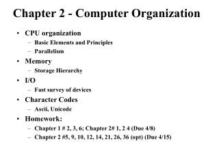
Chapter 2Machine Instructions And Programs • Instruction Set Architecture (ISA): • A complete instruction set is often referred to as ISA. • It also specifies the addressing methods used for accessing data operands and the processor registers available for use by the instructions.
2.1.1 Numbers Representation • Sign-and-magnitude • Change most significant bit from 0 to one for negative number • 1’s-complement • Complement each bit of the corresponding positive number for negative number • 2’s-complement most often used • Adding one to 1’s-complement number
B V alues represented Sign and b b b b magnitude 1' s complement 2' s complement 3 2 1 0 + 7 + 7 + 7 0 1 1 1 + 6 + 6 + 6 0 1 1 0 + 5 + 5 + 5 0 1 0 1 + 4 + 4 + 4 0 1 0 0 + 3 + 3 + 3 0 0 1 1 + 2 + 2 + 2 0 0 1 0 + 1 + 1 + 1 0 0 0 1 + 0 + 0 + 0 0 0 0 0 - 0 - 7 - 8 1 0 0 0 - 1 - 6 - 7 1 0 0 1 - 2 - 5 - 6 1 0 1 0 - 3 - 4 - 5 1 0 1 1 - 4 - 3 - 4 1 1 0 0 - 5 - 2 - 3 1 1 0 1 - 6 - 1 - 2 1 1 1 0 - 7 - 0 - 1 1 1 1 1 Figure 2.1. Binary, signed-integer representations.
2.1.2 Addition 0 1 0 1 + 0 + 0 + 1 + 1 0 1 1 1 0 Carry-out Figure 2.2. Addition of 1-bit numbers.
2.1.3 Addition and Subtraction of Signed Number • The rules governing the addition and subtraction of n-bit signed numbers using the 2’s-complement representation system: • To add two numbers, add their n-bit representation, ignoring the carry-out signal from the most significant bit (MSB) • To subtract two numbers X and Y, that is , to perform X-Y, form the 2’s-complement of Y and add it to X.
( + 4 ) 0 0 1 0 ( + 2 ) 0 1 0 0 ( ) 0 0 1 1 + 3 1 0 1 0 ( - 6 ) ( - 2 ) 0 1 0 1 ( + 5 ) 1 1 1 0 ( ) + 7 1 0 1 1 ( - 5 ) 0 1 1 1 1 1 1 0 ( - 2 ) 1 1 0 1 ( - 3 ) 1 0 0 1 ( - 7 ) 0 1 0 0 ( + 4 ) 1 1 0 1 1 1 0 1 ( - 3 ) 1 0 0 1 0 1 1 1 ( - 7 ) 0 1 0 0 ( + 4 ) 0 0 1 0 ( + 2 ) 0 0 1 0 ( ) 0 1 0 0 + 4 1 1 0 0 1 1 1 0 ( - 2 ) 0 1 1 0 0 1 1 0 ( + 6 ) ( + 3 ) 0 0 1 1 1 1 0 1 0 0 1 1 ( + 3 ) 1 0 0 1 1 0 0 1 ( - 7 ) 0 1 0 1 1 0 1 1 ( - 5 ) 1 1 1 0 ( - 2 ) 1 0 0 1 ( - 7 ) 1 0 0 1 0 0 0 1 ( + 1 ) 1 1 1 1 1 0 0 0 ( - 8 ) 0 0 1 0 0 0 1 0 ( + 2 ) 1 1 0 1 0 0 1 1 ( - 3 ) ( ) 0 1 0 1 + 5 (a) (b) + + (c) (d) + + (e) + - (f) - + (g) - + (h) - + (i) - + (j) - + Figure 2.4.2's-complement Add and Subtract operations.
2.1.3 Addition and Subtraction of Signed Number • Sign extension: • To represent a signed number in 2’s-complement form using a larger number of bits, repeat the sign bit as many times as needed to the left. • For example: 0001 (0000)0001 1011 (1111)1011
2.1.4 Overflow in Integer Arithmetic • n bit can represent values in he range -2n-1to + 2n-1 – 1. • For example: four bits (-8 to +7) • Add +7 and +4 -5 incorrect • Carry-out signal is 0 • Add -4 and -6 +6 incorrect • Carry-out signal is 1
2.1.4 Overflow in Integer Arithmetic • Overflow happens when adding two numbers having the same sign. • Carry out signal is not a sufficient indicator • Detection of overflow: • 1. When both operands X and Y have the same sign, and • 2. Overflow occurs when the sign of S (output SUM) is not the same as the signs of X and Y.
2.2 Memory Location And Addresses n bits first word second word • • • i th word • • • last word Figure 2.5. Memory words.
32 bits • • • b b b b 31 30 1 0 for positive numbers Sign bit: b = 0 31 for negative numbers b = 1 31 (a) A signed integer 8 bits 8 bits 8 bits 8 bits ASCII ASCII ASCII ASCII character character character character (b) Four characters Figure 2.6.Examples of encoded information in a 32-bit word.
2.2 Memory Location And Addresses • Accessing the memory to store or retrieve a single item of information, either a word or a byte, requires distinct names or addresses for each item location. • 24 bit address generates an address space of 224 which is 16 M.A 32 bit address creates an address space of 232 or 4G locations.
2.2.1 Byte Addressability • Byte-addressable memory is used. • Byte locations have addresses 0, 1, 2, 3, … if word length of the machine is 32 bits, successive words are located at the adresses 0, 4, 8, .. (one word = 4 bytes)
2.2.2 Big-Endian and Little-Endian Assignment W ord address Byte address Byte address 0 0 1 2 3 0 3 2 1 0 4 4 5 6 7 4 7 6 5 4 • • • • • • k k k k k k k k k k 2 - 4 2 - 4 2 - 3 2 - 2 2 - 1 2 - 4 2 - 1 2 - 2 2 - 3 2 - 4 (a) Big-endian assignment (b) Little-endian assignment Figure 2.7. Byte and word addressing.
2.3 Memory Operations • Load operation • The processor sends the address of the desired location to the memory and • Requests that its contents be read. • Store operation • The processor sends the address of the desired location to the memory together • With the data to be written into that location.
2.3 Memory Operations • Processor register can be either source or the destination o a transfer to or from the memory. • When a byte is transferred, it is usually located in the low-order byte position of the register.
2.4 Instruction and Instruction Sequencing • Data transfers between the memory and the processor registers • Arithmetic and logic operations on data • Program sequencing and control • I/O transfers
2.4.1 Register Transfer Notation • Memory location: LOC, PLACE, A, VAR2 • Processor register: R0, R5 • I/O register: DATAIN, OUTSTATUS • The content of a location [ ]: • For example: [LOC] • For example: R1[LOC]:?
2.4.1 Register Transfer Notation R3 [R1] + [R2]? Register Transfer Notation (RTN)
2.4.3 Basic Instruction Types • C= A + B C [A] + [B] • Three-address instruction Add A,B,C Where A, B are called source operands, C is called the destination operand Add is the operation.
2.4.3 Basic Instruction Types • A sequence of simpler instructions (two address instructions) to perform the same task Load A //copy the contents of memory location A into accumulator register Add B //add the contents of memory location A to the contents of accumulator registor Store C
2.4.3 Basic Instruction Types Load A, Ri Add B , Ri Store Ri, C • Generalization of the Load, Store and Add instruction given a general-purpose register.
2.4.3 Basic Instruction Types Add Ri, Rj • Instruction involves only operands that are in the registers. • For example, C=A+B Move A, Ri Move B, Rj Add Ri, Rj Move Rj, C
2.4.4 Intruction Execution and Straight-Line Sequence • C [A] + [B] • For the case of one memory operand and a number of registers. • 32 bits and the memory is byte address. • Straight line sequencing: • The address of the first instruction placed into the PC • The processor control circuit uses the information in the PC to fetch and execute instruction one at a time, in the order of increasing addresses.
2.4.4 Intruction Execution and Straight-Line Sequence • Two-phase procedure: • Instruction fetch • Instruction execution • The instruction is placed in IR
2.4.4 Intruction Execution and Straight-Line Sequence Address Contents i Begin execution here Move A,R0 3-instruction i + 4 program Add B,R0 segment i + 8 Move R0,C A Data for B the program C Figure 2.8. A program for C ¬ [A] + [B].
2.4.5 Branching Move NUM1,R0 i i + 4 Add NUM2,R0 i + 8 Add NUM3,R0 • • • i Add NUM n ,R0 + 4 n - 4 i 4 n + Move R0,SUM • • • SUM NUM1 NUM2 • • • NUM n Figure 2.9. A straight-line program for addingn numbers.
2.4.5 Branching Move N,R1 Clear R0 LOOP Determine address of "Next" number and add "Next" number to R0 Program loop Decrement R1 Branch>0 LOOP Move R0,SUM • • • SUM N n NUM1 NUM2 • • • NUM n Figure 2.10. Using a loop to addn numbers.
2.4.5 Branching • Assume the number of entries in the list, n, is stored in memory location N. • Register R1 is used as a counter to determine the number of loops executed. • Reduce R1 by 1 each time through the loop • Branch instruction: • Branch>0 Loop • //branch if greater than 0
2.4.6 Condition Codes • Keep tracking of information about the result of various operations for use by subsequent conditional instruction. • N(Negative) • Set to 1 if the result is negative ;otherwisse, cleared to 0 • Z(zero) • Set to 1 if the result is 0; otherwise, cleared to 0 • V(Overflow) • Set to 1 if arithmetic overflow; otherwise, cleared to 0 • C(Carry) • Set to 1 if a carry-out results from the operation; otherwise. Cleared to 0
2.4.6 Condition Codes • Example: branch>0 LOOP • The branch occurs if neither N nor Z. (It causes a branch if the value tested is neither negative nor equal to zero.)
2.5 Addressing Mode • The different ways in which the location of an operand is specified in an instruction are referred to as addressing mode. • See table 2.1
2.5.1 Implementation of Variables and Constants • Register mode – The operand is the contents of a processor register • Absolute mode – The operand is in a memory location • Immediate mode – Move 200, R0 Or Move #200, R0 //place 200 in register R0
2.5.1 Implementation of Variables and Constants • Example A = B + 6 Move B,R1 Add #6,R1 Move R1, A
2.5.2 Indirection and Pointers • Indirect Mode: The effective address of the operand is the contents of a register or memory location whose address appears in the instruction . • Place the name of the register or the memory address given in the instruction in parentheses. pointer
2.5.2 Indirection and Pointers Add (R1),R0 Add (A),R0 Main memory B Operand A B Register Operand R1 B B (a) Through a general-purpose register (b) Through a memory location Figure 2.11. Indirect addressing.
2.5.2 Indirection and Pointers • A = *B; //in c language Move (B),A or Move B, R1 Move (R1), A
2.5.3 Indexing and Array • Index mode • The effective address of the operand is generated by adding a constant value to the contents of a register EA = X + [Ri] or X(Ri) Ri is the index register