Download
1 / 43
430 likes | 609 Views
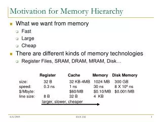
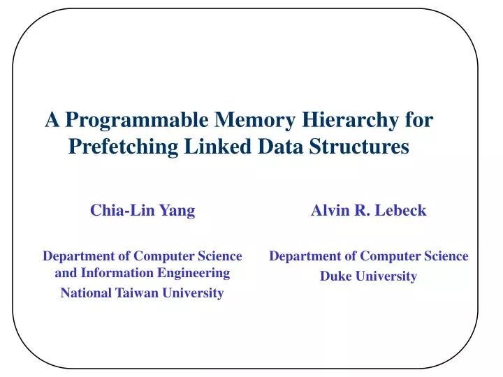
A Programmable Memory Hierarchy for Prefetching Linked Data Structures. Alvin R. Lebeck Department of Computer Science Duke University. Chia-Lin Yang Department of Computer Science and Information Engineering National Taiwan University. Memory Wall. Processor-memory gap grows over time

E N D
A Programmable Memory Hierarchy for Prefetching Linked Data Structures Alvin R. Lebeck Department of Computer Science Duke University Chia-Lin Yang Department of Computer Science and Information Engineering National Taiwan University
Memory Wall • Processor-memory gap grows over time • Prefetching • What ? Future Address Prediction • When? Prefetch Schedule CPU performance 60% yr Processor-Memory Gap DRAM performance 10% yr
Prefetch Linked Data Structures (LDS) p = head; while (p) { work (p->data); p = p -> next; } • Linked data structures • No regularity in the address stream • Adjacent elements are not necessarily contiguous in memory • Pointer-chasing problem p *p ….. currently visiting would like to prefetch while (p) { prefetch (p->next->next->next); work (p->data); p = p -> next; }
L1 L1 req L2 L2 req Main Memory Main Memory The Push Architecture • A LDS prefetching framework built on a novel data movement model - Push (Yang’2000) Traditional Pull Model New Push Model
Outline • Background & Motivation • What is the Push Architecture? • Design of the Push Architecture • Variations of the Push Architecture • Experimental Results • Related Research • Conclusion
Block Diagram of the Push Architecture prefetch req Prefetch Buffer Prefetch Engine L1 L2 Bus prefetch req Prefetch Engine L2 Memory Bus Main Memory prefetch req Prefetch Engine
How to Predict Future Addresses? • LDS traversal kernels • Load instructions in LDS traversal kernels are a compact representation of LDS accesses [Roth’98] • PFEs execute LDS traversal kernels independent of the CPU • The amount of computation between node accesses affects how far the PFE could run ahead of the CPU while ( list != NULL) { p =list->x; process (p->data); list =list->next;recurrent load }
x1 r1 a1 r2 x2 a2 r1 a1 r2 a2 x2 x1 a2 a2 x2 x1 2 a2 3 The Pointer-Chasing Problem: how does the push model help? L1 • Push model : pipelined process 1 2 3 4 L2 Main Memory PFE 1
2.Interaction Scheme 4. Redundant Prefetch 3. Synchronization between the CPU and PFE execution Push Architecture Design Issues 1. PFE Architecture Design CPU L1 controller PFE L2 controller PFE Main Memory controller PFE 5. Demands on the cache/memory controller
ISSUE #1: PFE Architecture • Programmable PFE • General purpose processor core • 5 stage pipeline, in-order processor • Integer ALU units for address calculation & control flow • TLB for address translation • Root register to store the root address of the LDS being traversed
store root address 1 x y 5 2 issue x 7 6 4 3 stop L1 PFE x x store [x] Issue #2: Interaction among PFEs CPU L1 Root Reg PFE Tree (root); : : Tree ( node) { if (node) { Tree (node->left); Tree (node->right); } } resume L2 Root Reg PFE resume Root Reg Mem PFE
Issue #3: Synchronization between CPU and PFEs • When do we need to synchronize the CPU and PFE execution? • Early prefetches • the PFEs are running too far ahead of the CPU • Useless prefetches • the PFEs are traversing down the wrong path • the PFEs are running behind the CPU • Throttle mechanism consume produce CPU PFE Prefetch Buffer
pull L1 L1 L1 push push push L2 L2 L2 Main Memory Main Memory Main Memory Variations of the Push Architecture PFE PFE push PFE PFE PFE PFE 3_PFE 2_PFE 1_PFE • 2_PFE should perform comparably to 3_PFE • 1_PFE performs well if most of LDS exist only in the main memory
Outline • Background & Motivation • What is the Push Architecture? • Design of the Push Architecture • Variations of the Push Architecture • Experimental Results • Related Research • Conclusion
Experimental Setup • SimpleScalar: out-of-order processor • Benchmark: • Olden benchmark suite & rayshade • Baseline processor: • 4-way issue, 64 RUU, 16 LSQ • lockup-free caches with 8 outstanding misses • 32KB, 32B line, 2-way L1 & 512K, 64B line, 4-way L2 • 84 cycle round-trip memory latency & 48 cycle DRAM access time • Prefetch model • Push model: 3 level PFEs, 32-entry fully-associative prefetch buffer • Pull model: L1 level PFE, 32-entry fully-associative prefetch buffer
Performance Comparison: Push vs. Pull • health, mst, perimeter and treeadd • Push: 4% to 25% speedup Pull: 0% to 4% speedup • em3d, rayshade • Push: 31% to 57% speedup Pull: 25% to 39% speedup • bh • Push: 33% speedup Pull: 33% speedup • Dynamically changing structures: bisort and tsp
Variations of the Push Architecture • 2_PFE performs comparably to 3_PFE • 1_PFE performs comparably to 3_PFE except for em3d.
Related Work • Prefetching for Irregular Applications: • Correlation based prefetch (Joseph’97 and Alexander’96) • Compiler based prefetch (Luk’96) • Dependence based prefetch (Roth’98) • Jump-pointer prefetch (Roth’99) • Decoupled Architecture • Decoupled Access Execute (Smith’82) • Pre-execution (Annavaram’2001,Collin’2001, Roth’2001, Zilles’2001, Luk’2001) • Processor-in-Memory • Berkley IRAM Group (Patterson’97) • Active Page (Oskin’98) • FlexRAM (Kang’99) • Impulse (Carter’99) • Memory-side prefetching (Hughes’2000)
Conclusion • Build a general architectural solution for the push model • The push model is effective in reducing the impact of the pointer-chasing problem on prefetching performance • applications with tight traversal loops • Push : 4% to 25% Pull: 0% to 4% • applications with longer computation between node accesses • Push : 31% to 57% Pull: 25% to 39% • 2_PFE performs comparably to 3_PFE.
Traversal Kernel void *HashLookup(int key, hash hash) { j = (hash->mapfunc)(key); for (ent = hash->array[j]; ent && ent->key != key; ent = ent->next); if (ent) return ent->entry; return Null; } CPU • traversal kernel identifier • hash->array[j] • key memory-mapped interface void kernel (HashEntry ent, int key) { for (ent ; ent && ent->key != key; ent = ent->next); } PFE
Block Diagram of Specialized PFE Recurrent Load Table Ready Queue (pc, base, offset) Root Register + Non-Recurrent Load Table + Kernel Id Register TLB Result Buffer (pc) Traversal-Info Table Instruction Buffer Cache/Memory Controller
local access global access Block Diagram of Programmable PFE Register File Root reg Processor Stack Instruction Cache Result Buffer Kernel Id Register TLB Instruction Buffer Kernel Index Table Cache/Memory Controller : memory-mapped structure
1 5 2 7 6 4 3 Issue #4: Redundant Prefetches • Redundant prefetches: • Tree traversals: L1 L2 Main Memory
Issue #4: Redundant Prefetches • Performance impact • Waste bus bandwidth • Memory accesses are satisfied more slowly in the lower level of memory hierarchy • Add a small data cache in the L2/Memory PFEs request Cache/Memory Controller miss request PFE Processor Data Cache result
demand/prefetch requests merge PFE PFE #Issue 5: Modifications to Cache/Memory Controller L1 demand requests merge MSHR L2 Bus Request Buffer L2 MSHR Memory Bus Main Memory Request Buffer
How to Avoid Early Prefetches? t1 t2 t3 2 5 5 3 3 3 4 4 4 1 1 2 2 9 9 3 6 10 13 3 6 10 13 4 5 7 8 11 12 14 15 4 5 7 8 11 12 14 15
How to Avoid Early Prefetches? t1 t3 2 PFE PFE 2 3 3 continue execution suspend execution 4 4 1 1 2 2 9 9 3 6 10 13 3 6 10 13 4 5 7 8 11 12 14 15 4 5 7 8 11 12 14 15
Mem PFE suspend execution How to Avoid Useless Prefetches? L1/L2 misses 1 2 3 4 5 6 L1 hits t1 Mem PFE :::::::: 2 2 3 3 trigger execution 4 4 1 2 3 4 5
Mem PFE suspend execution How to Avoid Useless Prefetches? L1/L2 misses 1 2 3 4 5 6 L1 hits t1 t2 Mem PFE Mem PFE 2 7 3 trigger execution trigger execution 4 1 2 3 4 5 6
Performance Prediction of the Push Architecture for Future Processors
Effect of the PFE Data Cache & Throttle Mechanism • The throttle mechanism has impact on bh. • The PFE data cache has impact on em3d, perimeter and treeadd
Effect of the PFE Data Cache % of redundant prefetches are captured in the PFE data cache Redundant Prefetch Distribution • em3d, perimeter, bh and treeadd : • 30% to 50% of prefetches are redundant • 70% to 100% of redundant prefetches • are captured in the PFE data cache
PFE Architecture :Effect of Wider Issue PFEs • Increasing issue width further improves performance, particularly • for em3d and treeadd
TLB Miss Effect • Hardware TLB miss handler, 30 cycle TLB miss penalty
PFE Architecture: Specialized vs. Programmable PFE • A programmable PFE can achieve performance comparable to • a specialized PFE
Breadth-First Tree Traversal 1 Traversal Kernel list = head; while (list) { node = list->ptr; left = node->left; right = node->right; list = list->next; } 2 3 4 5 6 7 8 9 10 11 12 13 14 15 :::::::::::::::::::::::::::::::::::::::::::::::: Head Tail 8 9 10 ::: 13 14 15
2.Interaction Scheme 3. Redundant Prefetch 4. Synchronization between the CPU and PFE execution Push Architecture Design Issues 1. PFE Architecture Design CPU L1 controller PFE L2 controller PFE Main Memory controller PFE 5. Demands on the cache/memory controller
1 5 2 x y 7 6 4 3 Restore PFE State Register File PC x issued: 400988 x miss: 400990, 400950 - 400978 y issued: 400998 00400950 addiu $sp[29],$sp[29],-56 00400958 sw $ra[31],48($sp[29]) 00400960 sw $s8[30],44($sp[29]) 00400968 sw $s0[16],40($sp[29]) 00400970 addu $s8[30],$zero[0],$sp[29] 00400978 addu $s0[16],$zero[0],$a0[4] 00400980 beq $s0[16],$zero[0],004009a8 (x)00400988 lw $a0[4],4($s0[16])miss 00400990 jal 00400950 <K_TreeAdd> (y)00400998 lw $a0[4],8($s0[16]) 004009a0 jal 00400950 <K_TreeAdd> 004009a8 addu $sp[29],$zero[0],$s8[30] 004009b0 lw $ra[31],48($sp[29]) 004009b8 lw $s8[30],44($sp[29]) 004009c0 lw $s0[16],40($sp[29]) :::::::::: save registers in the stack restore registers from the stack
Restore PFE State • Correct resume PC • Statically construct the resume PC table