Download
1 / 1
10 likes | 100 Views
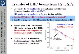
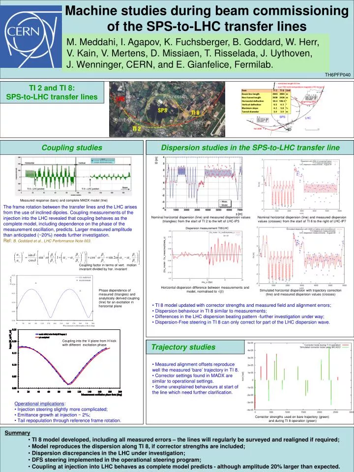
Machine studies during beam commissioning of the SPS-to-LHC transfer lines. M. Meddahi, I. Agapov, K. Fuchsberger, B. Goddard, W. Herr, V. Kain, V. Mertens, D. Missiaen, T. Risselada, J. Uythoven, J. Wenninger, CERN, and E. Gianfelice, Fermilab. TH6PFP040. TI 2 and TI 8:

E N D
Machine studies during beam commissioning of the SPS-to-LHC transfer lines M. Meddahi, I. Agapov, K. Fuchsberger, B. Goddard, W. Herr, V. Kain, V. Mertens, D. Missiaen, T. Risselada, J. Uythoven, J. Wenninger, CERN, and E. Gianfelice, Fermilab. TH6PFP040 TI 2 and TI 8: SPS-to-LHC transfer lines Coupling studies Dispersion studies in the SPS-to-LHC transfer line Measured response (bars) and complete MADX model (line) The frame rotation between the transfer lines and the LHC arises from the use of inclined dipoles. Coupling measurements of the injection into the LHC revealed that coupling behaves as the complete model, including dependence on the phase of the measurement oscillation, predicts. Larger measured amplitude than anticipated (~20%) needs further investigation. Ref: B. Goddard et al., LHC Performance Note 003. Nominal horizontal dispersion (line) and measured dispersion values (triangles) from the start of TI 2 to the left of LHC-IP3 Nominal horizontal dispersion (line) and measured dispersion values (crosses) from the start of TI 8 to the right of LHC-IP7 Coupling factor in terms of vert. motion invariant divided by hor. invariant Horizontal dispersion difference between measurements and model, normalised to √(b) Phase dependence of measured (triangles) and analytically derived coupling (line) for an excitation in horizontal plane Simulated horizontal dispersion with trajectory correction (line) and measured dispersion values (crosses) • TI 8 model updated with corrector strengths and measured field and alignment errors; • Dispersion behaviour in TI 8 similar to measurements; • Differences in the LHC dispersion beating pattern -further investigation under way; • Dispersion-Free steering in TI 8 can only correct for part of the LHC dispersion wave. Coupling into the V plane from H kick with different excitation phase Trajectory studies • Measured alignment offsets reproduce well the measured ‘bare’ trajectory in TI 8. • Corrector settings found in MADX are similar to operational settings. • Some unexplained behaviours at start of the line which need further clarification. • Operational implications: • Injection steering slightly more complicated; • Emittance growth at injection ~ 2%; • Tail repopulation through reference frame rotation. Corrector strengths used on bare trajectory (green) and during TI 8 operation (green) • Summary • TI 8 model developed, including all measured errors – the lines will regularly be surveyed and realigned if required; • Model reproduces the dispersion along TI 8, if corrector strengths are included; • Dispersion discrepancies in the LHC under investigation; • DFS steering implemented in the operational steering program; • Coupling at injection into LHC behaves as complete model predicts - although amplitude 20% larger than expected.