Download
1 / 19
190 likes | 372 Views
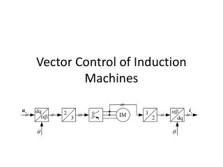
Concepts of Vector-Sum Control for CW-operation. C.Schmidt, S.Simrock DESY. ERL07, WG3. Outline. Principle of vector sum control High Q l cavities and microphonics Simulation results Calibration errors Summary. Vector Sum (VS) Control?. FF. FF. c. Advantage

E N D
Concepts of Vector-Sum Control for CW-operation C.Schmidt, S.Simrock DESY ERL07, WG3
Outline • Principle of vector sum control • High Ql cavities and microphonics • Simulation results • Calibration errors • Summary
Vector Sum (VS) Control? FF FF c Advantage • Cost argument: one high-power klystron is cheaper than several smaller ones! • Cost ~ power • Only one LLRF system for multiple cavities is required Disadvantage • VS Calibration required • Only small parameters tolerances allowed • Loaded Q and detuning • RF power distribution ( amplitude and phase ) c SP calibration SP feedback loop VS calculation
gradient deviation individual cavity gradient General Definitions cavity differential equation Vector sum (VS) N number of cavities deviation in the individual cavity fields are caused by detuning effects like microphonics.
Cavity Resonance Curve resonance frequency of the cavity changes because of microphonic oscillations during time. |V| t3 t1 t2 1 w1/2 0.7 microphonic oscillation detuning of a full bandwidth leads to power drop of 50%! 1/fm wrf (wrf+ ADf) (wrf- ADf) w0
Vector Sum of N Cavities detuning angle FB-Signal SP gradient Vector sum calibration can only be done to certain accuracy! DV FB-Signal measured calibration error SP Gradient real cavity gradient In presence of microphonic noise the actual field vector as seen by the beam will fluctuate, even if the measured vector is held constant, if the VS errors are non zero. Even with well regulated vector sum, individual cavity gradients can fluctuate.
Simulink Model • variable number of cavities • decoupled cavities • no lorentz force detuning model parameters:
Scenario 1 worst case assumption: (N-1) - cavities oscillate with same microphonic vibration N - cavity is microphonic-free feedback will lead to increase in gradient of cavity N
Max Gradient in Resonant Cavity Dw=w1/2 VS of 8 cavities increasing # of cavities leads to a limit peak gradient small detuning ~ for high frequency microphonics (> w1/2 ) effect becomes much smaller
Microphonic simulations vector sum of 8 cavities, where cav.1-7 have different oscillations and cav. 8 (Dw=0) gives observation data Assume sinusoidal microphonics. some statistics included with Frequency spread over cavities (10-20 / 100-200 Hz) Real microphonics have totaly different probability distribution. i.e peak gradient excursions will be rare. Ref. Microphonics Measurements in SRF Cavities for Ria, Proceedings of 2003 PAC
40% V/m V/m fm=10-20 Hz / ADf = w1/2
Q induced angle error Q angle calibration error induced amplitude error Amplitude calibration error I I Calibration Error Amplitude and phase error A.Brand A.Brand
fb=beam phase 0.03 rad = 1.7° w. beam 0.003 rad = 0.17° w.o. beam 0.03 rad = 1.7° 0.003rad = 0.17° Field Stability and Calibration Error estimation of the calibration error: If its possible to measure the field vector with an accuracy of 0.3%, then the vector sum can be calibrated with an accuracy of 3% and 1.7 degrees
Summary • Vector sum control should be considered for cw operation of high loaded Q cavities • The simulations presented demonstrate that microphonic levels of two bandwidths (fm >100 Hz) or half bandwidths (fm < 20 Hz) can be accepted • Peak gradient and power excursions will occur very rarely for real microphonic probability distributions. Operational procedures could be developed to allow higher microphonics. • further studies including vector sum calibration requirements with real microphonics distributions will improve quantitative understanding
0.085% V/m V/m fm=100-200 Hz / ADf = 0.25 w1/2
5.5% V/m V/m fm=100 - 200 Hz / ADf = 2 w1/2
1.4% V/m V/m fm=100-200 Hz / ADf = w1/2
10.1% V/m V/m fm=10-20 Hz / ADf = 0.5 w1/2