Download
1 / 64
650 likes | 824 Views
Multisource Least-squares Migration and Prism Wave Reverse Time Migration. Wei Dai. Oct. 31, 2012. Outline. Introduction and Overview Chapter 2: Multisource least-squares migration Chapter 3: Plane-wave least-squares reverse time migration Chapter 4: Prism wave reverse time migration

E N D
Multisource Least-squares Migration and Prism Wave Reverse Time Migration Wei Dai Oct. 31, 2012
Outline Introduction and Overview Chapter 2: Multisource least-squares migration Chapter 3: Plane-wave least-squares reverse time migration Chapter 4: Prism wave reverse time migration Summary
Introduction: Least-squares Migration • Seismic migration: Given: Observed data • modelling operator Migration velocity Goal: find a reflectivity model to explain by solving the equation • expensive Direct solution: Conventional migration: • Iterative solution:
Introduction: Motivation for LSM • Problems in conventional migration image 0 Z (km) migration artifacts 3 0 X (km) 6 0 X (km) 6 imbalanced amplitude
Problem of LSM • Least-squares migration has been shown to produce high quality images, but it is considered too expensive for practical imaging. • Solution: combine multisource technique and least-squares migration (MLSM).
Multisource Migration Image Motivation for Multisource • Problem: LSM is too slow Many (i.e. 20) times slower than standard migration • Solution: multisource phase-encoding technique Multisource Crosstalk • Multisource LSM • To: • Increase efficiency • Remove artifacts • Suppress crosstalk
Overview • Chapter 2 : MLSM is implemented with Kirchhoff migration method and the performance is analysed with signal-to-noise ratio measurements. • Chapter 3: MLSM is implemented with reverse time migration and plane-wave encoding. • Chapter 4: A new method is proposed to migrate prism waves with reverse time migration.
Outline Introduction and Overview Chapter 2: Multisource least-squares migration Chapter 3: Plane-wave least-squares reverse time migration Chapter 4: Prism wave reverse time migration Summary
Random Time Shift Random source time shifts O(1/S) cost! Encoding Matrix Supergather Encoded supergather modeler
Multisource Migration Given: Supergathermodeller shots are encoded in the supergather Define: Supergather migration )
Multisource Migration ) 1 Signal term S-1 noise terms SNR Repeat for all the shots SNR The signal-to-noise ratio of the migration image from one supergather is 1, when . If there are more supergathers SNR is the number of stacks.
Numerical Verification Image of One supergather True Model Conventional Image 0 Z (km) 1.5 0 X (km) 5 0 X (km) 5
Numerical Verification Image of Isupergathers True Model Conventional Image 0 Z (km) 1.5 0 X (km) 5 0 X (km) 5
Multisource LSM One supergather, static encoding Iteration: 1 Iteration: 30 Iteration: 10 Iteration: 60 True Model 0 Z (km) 1.5 0 X (km) 5 0 X (km) 5
Multisource LSM One supergather, dynamic encoding Iteration: 1 Iteration: 10 Iteration: 30 Iteration: 60 True Model 0 Z (km) 1.5 0 X (km) 5 0 X (km) 5
Static vs Dynamic dynamic Static Iteration: 1 Iteration: 1 Iteration: 30 Iteration: 60 Iteration: 10 Iteration: 60 Iteration: 30 Iteration: 10 0 Z (km) 1.5 0 X (km) 5 0 X (km) 5
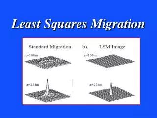
Chapter 2: Conclusions • MLSM can produce high quality images efficiently. • LSM produces high quality image. • Multisource technique increases computational efficiency. • SNR analysis suggests that not too many iterations are needed.
Chapter 2: Limitations • MLSM implemented with Kirchhoff migration can only reduce I/O cost. • need to be implemented with reverse time migration. • Random encoding method requires fixed spread acquisition geometry. • Plane-wave encoding.
Limitation of Random Encoding • It is not applicable to marine streamer data. Fixed spread geometry (synthetic) Marine streamer geometry (observed) 6 traces 4 traces Mismatch between acquisition geometries will dominate the misfit.
Outline Introduction and Overview Chapter 2: Multisource least-squares migration Chapter 3: Plane-wave least-squares reverse time migration Chapter 4: Prism wave reverse time migration Summary
Chapter 3: Plane-wave LSRTM • Implemented with wave-equation based method • Significant computation saving. • Plane-wave encoding • Applicable to marine-streamer data. • Instead of inverting for one stacked image, image from each shot is separated. • Common image gathers are available. • Good convergence even with bulk velocity error.
Plane Wave Encoding d(p,g,t)= p= Δt=pxs θ xs 0
Plane Wave Encoding A common shot gather A supergather (p=0 μs/m) 0 Time (s) 12 0 X (km) 12 0 X (km) 12
Least-squares Migration with Prestack Image • Equation: = m • Equations with stacked image: • Equations with prestatck image: = • Misfit: Solution:
Theory: Least-squares Migration + • Misfit: Penalty on image difference of nearby angles -d)-λ • Gradient:
Prestack Images • Prestack image: X X stack p Z extract Z
The Marmousi2 Model • Model size: 801 x 351 • Source freq: 20 hz • shots: 801 • geophones: 801 • Plane-wave gathers: 31 km/s 0 4.5 Z (km) 3.5 1.5 8 0 X (km)
Smooth Migration Velocity 0 Z (km) 3.5 Conventional RTM Image 0 Z (km) 3.5 0 X (km) 8
Plane-wave RTM image 0 Z (km) 3.5 Plane-wave LSRTM image (30 iterations) 0 Z (km) 3.5 0 X (km) 8
Common Image Gathers from RTM Image 0 Z (km) 3.5 Common Image Gathers from LSRTM Image 0 Z (km) 3.5 0 X (km) 8
RTM Image /w 5% Velocity Error 0 Z (km) 3.5 LSRTM Image /w 5% Velocity Error 0 Z (km) 3.5 0 X (km) 8
CIGs from RTM Image /w 5% Velocity Error 0 Z (km) 3.5 CIGs from LSRTM Image /w 5% Velocity Error 0 Z (km) 3.5 0 X (km) 8
Plane-wave LSRTM of 2D Marine Data • Model size: 16 x 2.5 km • Source freq: 25 hz • Shots: 515 • Cable: 6km • Receivers: 480 km/s 0 2.1 Z (km) 2.5 1.5 16 0 X (km)
Workflow Raw data Transform into CDP domain Apply Normal Moveout to flat reflections 2D spline interpolation Shift all the events back Transform into CRG domain Tau-p transform in CRG domain to generate plane waves
Conventional RTM (cost: 1) 0 Z (km) 2.5 Plane-wave RTM (cost: 0.2) 0 Z (km) 2.5 16 0 X (km)
Plane-wave LSRTM (cost: 12) 0 Z (km) 2.5 Plane-wave LSRTM /w One Angle per Iteration (cost: 0.4) 0 Z (km) 2.5 0 16 X (km)
Zoom Views Conventional RTM Plane-wave LSRTM Plane-wave LSRTM (one angle) Plane-wave RTM
Zoom Views Conventional RTM Plane-wave LSRTM Plane-wave LSRTM (one angle) Plane-wave RTM
Observed Data vs Predicted Data (Plane Waves) Observed Data Predicted Data 0 Time (s) 3 0 X (km) 3.75 0 X (km) 3.75
Plane waves are fitted perfectly Observed Data (Red lines) vs Predicted Data (Black lines) Amplitude 0 Time (s) 3
Chapter 3: Conclusions • Plane-wave LSRTM can efficiently produce high quality images. • LSM produces high quality image. • Plane-wave encoding applicable to marine data. • Prestack image incorporated to produce common image gathers and enhance robustness.
Limitations • Prestack images need to be stored during iterations. • Large memory cost.. • Plane wave encoding. • Regular sampling in shot axis is required (interpolation). • Sufficient amount of angles to reduce aliasing artifacts (i.e. 31).
Outline Introduction and Overview Chapter 2: Multisource least-squares migration Chapter 3: Plane-wave least-squares reverse time migration Chapter 4: Prism wave reverse time migration Summary
Chapter 4: Introduction • Problem: Vertical boundaries (salt flanks) are difficult to image because they are usually not illuminated by primary reflections. • Solution: Prism waves contain valuable information.
Conventional Method • When the known boundaries are embedded in the velocity model, conventional RTM can migrate prism waves correctly.
Recorded Trace 0 2 Time (s)