Download
1 / 19
190 likes | 346 Views
Sandia M.A.S.T. Miniature Automated Shock Tester. TEAM PICTURE HERE. Nicholai Olson, Cameron Hjeltness, Travis Nebeker, Michael Brewster, Fernando De La Garza. Client: Dr. Scott Whalen - Sandia National Laboratories Faculty Advisor: Dr. Steve Beyerlein

E N D
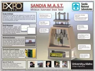
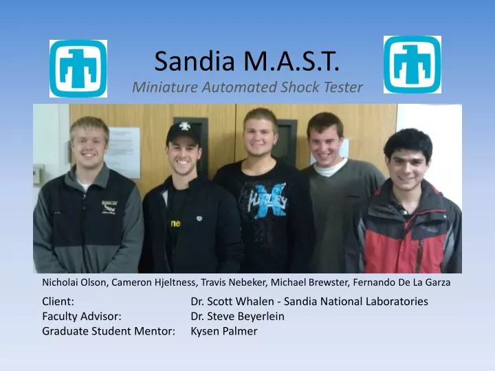
Sandia M.A.S.T. Miniature Automated Shock Tester TEAM PICTURE HERE Nicholai Olson, Cameron Hjeltness, Travis Nebeker, Michael Brewster, Fernando De La Garza Client: Dr. Scott Whalen - Sandia National Laboratories Faculty Advisor: Dr. Steve Beyerlein Graduate Student Mentor: KysenPalmer
What is a Shock Tester? • Used for testing hardware under impact loading conditions • Come in different sizes for testing a variety of objects • Typically use pneumatics, gravity, electric actuation
Background Dr. Whalen – Sponsor and Client • Needs personal, bench-top sized test apparatus • Measuring shock levels on small electronics • Safety conditions exist • Lab constraints
Benefits of this Project • Unlimited access to a personal tester reduces design cycle time • Smaller apparatus than commercially available • High accuracy ensures design reliability • Specific design constraints are tailored toward the specific needs of Dr. Whalen.
Project Targets • Measure shock of magnitude 100g to 200g • Haversine waveform required • Maximum dimensions: 30” W x 30” L x 72” H • Smallest possible design preferred • Device under test (DUT): D = 5 cm L = 8 cm M = 0.3 kg • Fixture to conform to Sandia standard bolt pattern • LabView software used to collect data • Safety shields and safety mechanisms to be installed
Prototype Development Slide Rails Accelerometer and DUT Mounting Galvanized Steel Pipe Construction
Prototype Goals • Verification of design calculations • Debug accelerometer & hardware • Develop data acquisition program
Accelerometer Target Values • Large frequency range (upper end ~10 [kHz]) • Data filter included within the unit • Small form-factor • Resists influences by temperature changes • Relatively low price (Under $1,300.00) • Accessories included
Accelerometer Purchased X-Y-Z Outputs and Constant Current Inputs Triaxial Accelerometer • PCB Piezotronics Model 356A24 • 500 g peak acceleration measurement • 1 - 9000 Hz Frequency Range
Structural Considerations • Four Post • Stable • Possible galling • High cost • Machining time • Two Post • Low chance of galling • Medium-Low cost • Requires higher strength material
Reduction of Energy Loss • Bearings • Less friction • Higher cost Both options may be viable. • Bushings • More friction • Lower cost
Viable Design Options Option B: ACME Screw Actuation Option A: Linear Motor / Solenoid
Table Lift System Option A: Option B: • Solenoid • Medium cost • Easily Programmable • Linear motor • High cost • High difficulty of Programming • Both • Accurate and repeatable • Simplify system • ACME Screw • Strong • Low cost and high reliability • Low repeatability
Release Mechanism Option A: Linear Motor / Solenoid • Solenoid and Pin • High Cost • High Safety • Difficult control system • No release mechanism needed Option B: ACME Screw • Magnetic Release • Works with ACME screw idea • Requires dual control to re-couple
Downward Acceleration Option A: • Linear Motor /Solenoid • Variable Force Input • Very Controllable Option B: • Gravity • No cost • Longer travel required • Springs/Elastic • Low cost • Workable area reduced
Post-Impact Energy Dissipation Option A: Linear Motor / Solenoid • Controls can be reversed to prevent ringing • Viscoelastic Dampers • Typically Low cost • Easy to install/vary • Locking Mechanism • Fast stop • May cause ringing • Increased machining time Option B: ACME Screw • Solenoid • Medium cost • Highly controllable • Electromagnetic Stopper • Easily Programmable • Medium cost • May cause ringing
Method to Vary Shock / Waveform • Variable Elastic Stiffness • Springs in parallel • Increase Spring Constant • Acceleration at Impact • Vary Drop Height • Change force input • Few components required • Vary Stiffness of base • Changing modulus of elasticity • Adding or subtracting material can change pulse length and wave form. A combination of these may be used.
Next Steps • Develop data acquisition program • Prototype testing • Develop detailed design • Purchase components • Fabrication • Testing and validation • Deliver finished product to Dr. Whalen