Download

1 / 26
260 likes | 492 Views
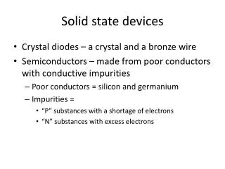
Solid State Devices I. Benchmark Companies Inc PO Box 473768 Aurora CO 80047. Transformers. Objectives: Definition of Transformer Uses of a Transformer Step-Up Step-Down Isolator. Back. Transformers. Back. Transformers. Symbol. Primary. :. Secondary. N P. :. N S.

E N D
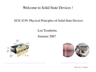
Solid State Devices I Benchmark Companies Inc PO Box 473768 Aurora CO 80047
Transformers • Objectives: • Definition of Transformer • Uses of a Transformer • Step-Up • Step-Down • Isolator Back
Transformers Back
Transformers Symbol Primary : Secondary NP : NS A transformer typically has two separate windings with a Varying number of turns (N). They are the primary winding And Secondary winding Back
Transformers Symbol Primary : Secondary NP : NS The two lines in the center of the two coils indicate this Transformer has a core. (No lines indicates no core) Back
Transformers Symbol Primary : Secondary NP : NS There is another type of transformer called a center-tap transformer (photo). It has many uses in today’s electronics Back
Transformers Symbol Primary : Secondary NP : NS The benefit of center-tap transformers is the availability of several voltage levels on the secondary winding. Back
Transformers Virtually every electronic devices which uses AC has to convert the power to a usable level. Back
Transformers Symbol Primary : Secondary A transformer is a typically a pair of coils where ones magnetic field acts on the other Back
Transformers Symbol Primary : Secondary The flow of current through the primary causes current to flow in the opposite direction in the secondary. Back
Transformers Symbol Primary : Secondary The direction of current is designated by dots on either end of the windings. Back
Transformers Symbol Primary : Secondary NP : NS RECALL current flows through the primary winding, a magnetic field is produced that causes a current to flow through the secondary winding. Back
Transformers Symbol Primary : Secondary NP : NS The current flowing through the primary winding causes the current to flow in an opposite direction through the secondary. Back
Transformers Symbol Primary : Secondary NP : NS The current direction is indicated by the dots on each coil. Having the dot on the same end tells us the output is in phase. Back
Transformers Symbol Primary : Secondary NP : NS Output Voltage is directly proportional to the number of Turns in the secondary winding (Ns) with respect to the Primary windings(Np). This is called the Turns Ratio. Back
Transformers Symbol Primary : Secondary NP : NS The relationship is defined as follows: Ep/Es = Np/Ns Back
Transformers NP : NS Example: Primary winding has 20 turns and the Secondary Winding has 40 turns. The result is the input voltage is Increased by a factor of 2 . 10/V(out) = 20/40 >> 400/20 = V(out) = 20 volts. This is a Step-up Transformer Back
Transformers NP : NS Likewise, if a Primary winding has 40 turns and the Secondary Winding has 20 turns. The result is the input voltage is decreased by ½. 10/V(out) = 40/20 >> 200/40 = V(out) = 5 volts. This is a Step-down Transformer Back
Transformers NP : NS Sometimes, there is a need to isolate voltage source from the Circuit. This can be done by using a transformer with a 1:1 Turns ratio Back
Transformers NP : NS You should understand that there is no net power loss In an ideal transformer. That means that: Power (primary) = Power (secondary) Ip*Ep = Is*Es Back
Transformers Current (in) Current (out) Voltage (out) Voltage (in) NP : NS Moving Ip and Is to one side of the equal sign and Ep and Es to the other yields: Ip/Is = Es/Ep (Inversely Proportional) Back
Transformers NP : NS Transformers and the secondary circuit have a loading Effect on the source voltage that is proportional to the Turns ratio Np/Ns x R1 = RL Back
Transformers NP : NS Example: Primary winding has 20 turns and the Secondary Winding has 40 turns. If R1 = 10KOhms the Load Resistance (RL) = (20/40)x10k = 5kOhms. Note the difference in expected current needed to drive the circuit. Back
Transformers Summary on Transformers Formulas: Vin/Vout = Np/Ns Iin/Iout = Ns/Np Pin = Pout Np/Ns x R1 = RL The Formulas above of are based on the assumption that The transformer is ideal and no power loss occurs in the Transformer. Back
Transformer TransformersSummary Transformers take a waveform and scale the waveform according to the turns ratio of the primary coil with respect to the secondary coil. If the turns ratio is greater than 1 the waveform is increased, if the ratio is less than one, the waveform is decreased. Scaled Waveform Sine wave input Back
End of Presentation Back