Download
1 / 37

E N D
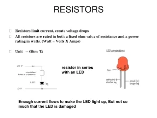
RESISTORS • Jamnas P A • Faculty(T&D) • Kaynes Technology, Mananthavady
Resistors Topics Covered 1: Types of Resistors 2: Resistor Color Coding 3: Variable Resistors 4: Rheostats and Potentiometers 5: Power Ratings of Resistors 6: Resistor Troubles
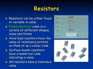
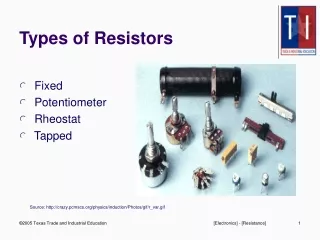
Cntd… • Types of Resistors • Wire-wound resistors • Carbon-composition resistors • Film-type resistors • Carbon film • Metal film • Surface-mount resistors (chip resistors) • Fusible resistors • Thermistors
Cntd.. • Wire Wound Resistor • Special resistance wire is wrapped around an insulating core, typically porcelain, cement, or pressed paper. • These resistors are typically used for high-current applications with low resistance and appreciable power. Fig. 2-3: Large wire-wound resistors with 50-W power ratings. (a) Fixed R, length of 5 in. (b) Variable R, diameter of 3 in.
Cntd.. • Carbon Composition Resistors • Made of carbon or graphite mixed with a powdered insulating material. • Metal caps with tinned copper wire (called axial leads) are joined to the ends of the carbon resistance element. They are used for soldering the connections into a circuit. • Becoming obsolete because of the development of carbon-film resistors. Fig. 2-2: Carbon resistors with the same physical size but different resistance values. The physical size indicates a power rating of ½ W.
Cntd… Carbon Film Resistors • Compared to carbon composition resistors, carbon-film resistors have tighter tolerances, are less sensitive to temperature changes and aging, and generate less noise. Fig. 2-4: Construction of a carbon film resistor.
Cntd… • Metal Film Resistors • Metal film resistors have very tight tolerances, are less sensitive to temperature changes and aging, and generate less noise. Fig. 2-5: Construction of a metal film resistor.
Cntd.. • Surface-Mount Resistors (also called chip resistors) • These resistors are: • Temperature-stable and rugged • Their end electrodes are soldered directly to a circuit board. • Much smaller than conventional resistors with axial leads. • Power dissipation rating is usually 1/8 to ¼ W Fig. 2-6: Typical chip resistors.
Cntd.. • Fusible Resistors: • Fusible resistors are wire-wound resistors made to burn open easily when the power rating is exceeded. They serve a dual function as both a fuse and a resistor.
2: Resistor Color Coding • Carbon resistors are small, so their R value in ohms is marked using a color-coding system. • Colors represent numerical values. • Coding is standardized by the Electronic Industries Alliance (EIA).
Resistor Color Coding Resistor Color Code Color Code 0 Black 1 Brown 2 Red 3 Orange 4 Yellow 5 Green 6 Blue 7 Violet 8 Gray 9 White Fig. 2-8: How to read color stripes on carbon resistors for R in ohms.
Resistor Color Coding • Resistors under 10 Ω: • The multiplier band is either gold or silver. • For gold, multiply by 0.1. • For silver, multiply by 0.01. Fig. 2-9: Examples of color-coded R values, with percent tolerance.
Yellow = 4 Resistor Color Coding • Applying the Color Code • The amount by which the actual R can differ from the color-coded value is its tolerance. Tolerance is usually stated in percentages.
1 kW (950 to 1050 W) 390 W (370.5 to 409.5 W) 22 kW (20.9 to 23.1 kW) 1 MW (950 kW to 1.05 MW) Resistor Color Coding • What is the nominal value and permissible ohmic range for each resistor shown?
Resistor Color Coding • Five-Band Color Code • Precision resistors often use a five-band code to obtain more accurate R values. • The first three stripes indicate the first 3 digits in the R value. • The fourth stripe is the multiplier. • The tolerance is given by the fifth stripe. • Brown = 1% • Red = 2% • Green = 0.5% • Blue = 0.25% • Violet = 0.1%. Fig. 2-10: Five-band code.
Color Code 0 Black 1 Brown 2 Red 3 Orange 4 Yellow 5 Green 6 Blue 7 Violet 8 Gray 9 White Problem • Using the five-band code, indicate the colors of the bands for each of the following resistors: • 110 Ω ± 1% • 34 kΩ ± 0.5% • 82.5 kΩ ± 2% Tolerance Brown = 1% Red = 2% Green = 0.5% Blue = 0.25% Violet = 0.1%.
Resistor Color Coding • Zero-Ohm Resistor • Has zero ohms of resistance. • Used for connecting two points on a printed-circuit board. • Body has a single black band around it. • Wattage ratings are typically 1/8- or 1/4-watt. A zero-ohm resistor is indicated by a single black color band around the body of the resistor.
Chip Resistor Coding System • Body color is usually white or off-white • End terminals are C-shaped • Three (four) digits on the body or on the film • First 2 (3) digits indicate the first two (three) numbers • Third (fourth) digit indicates the multiplier • Are available in tolerances of ±1% ±5% but tolerances are not indicated on the chip • The letter R is used to signify a decimal point for values between 1 to 10 ohms (1R5 means 1.5 ohms)
3: Variable Resistors • A variable resistor is a resistor whose resistance value can be changed.
3-1: Thermistor • Thermistors: • Thermistors are temperature-sensitive resistors whose resistance value changes with changes in operating temperature. • Used in electronic circuits where temperature measurement, control, and compensation are desired. Typical thermistor shapes and sizes.
3-4: Rheostats • Rheostats are variable resistances used to vary the amount of current or voltage in a circuit. • Rheostats: • Two terminals. • Connected in series with the load and the voltage source. • Varies the current.
3-5: Potentiometers • Potentiometers: • Three terminals. • Ends connected across the voltage source. • Third variable arm taps off part of the voltage.
Rheostats and Potentiometers • Potentiometers • Potentiometers are three-terminal devices. • The applied V is input to the two end terminals of the potentiometer. • The variable V is output between the variable arm and an end terminal. Fig. 2-18: Potentiometer connected across voltage source to function as a voltage divider. (a) Wiring diagram. (b) Schematic diagram.
Potentiometer Used as a Rheostat • A potentiometer may be used as a rheostat by simply using the wiper terminal and one of the other terminals, the third terminal is left unconnected and unused • Another method is to wire the unused terminal to the center terminal
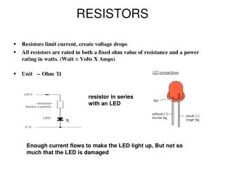
Power Rating of Resistors • In addition to having the required ohms value, a resistor should have a wattage rating high enough to dissipate the power produced by the current without becoming too hot. • Power rating depends on the resistor’s construction. • A larger physical size indicates a higher power rating. • Higher-wattage resistors can operate at higher temperatures. • Wire-wound resistors are physically larger and have higher power ratings than carbon resistors.
1 kW,5% nominal W 1.5 kW Resistor Troubles An open resistor measures infinite resistance. An example of an out-of-tolerance resistor:
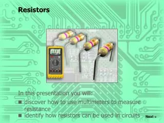
Resistor Troubles • Resistance measurements are made with an ohmmeter. • The ohmmeter has its own voltage source, so voltage must be off in the circuit being tested. Otherwise the ohmmeter may become damaged.
Resistor Troubles • All experienced technicians have seen a burnt resistor. • This is usually caused by a short somewhere else in the circuit which causes a high current to flow in the resistor. • When a resistor’s power rating is exceeded, it can burn open or drift way out of tolerance.