Download
1 / 13
130 likes | 236 Views
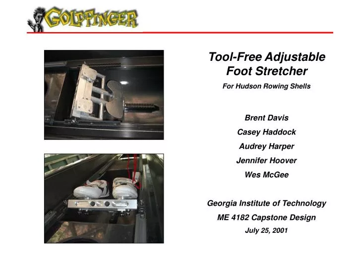
Tool-Free Adjustable Foot Stretcher For Hudson Rowing Shells Brent Davis Casey Haddock Audrey Harper Jennifer Hoover Wes McGee Georgia Institute of Technology ME 4182 Capstone Design July 25, 2001. Agenda. Background Current Design Overview Design Concepts Selection Methods

E N D
Tool-Free Adjustable Foot Stretcher For Hudson Rowing Shells Brent Davis Casey Haddock Audrey Harper Jennifer Hoover Wes McGee Georgia Institute of Technology ME 4182 Capstone Design July 25, 2001
Agenda • Background • Current Design Overview • Design Concepts Selection Methods • Part Drawings • Engineering Analysis • Prototype Construction & Demo
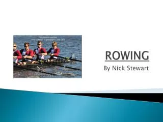
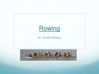
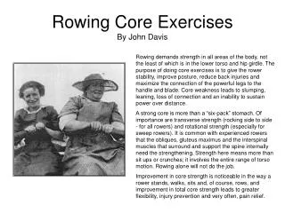
Background • What’s a rowing shell? • A rowing shell is a small, lightweight boat used in crew racing • What’s a foot stretcher? • The rower’s shoes (and feet) are securely held to this part of the boat • The rower pushes off the foot stretcher during the stroke to propel the boat through the water
Current Design • What’s right with the current foot stretcher? • Lightweight (~ 1.5 lbs.) • Durable • What’s wrong with the current foot stretcher? • Adjustments must be made using tools • Some adjustments can’t be made at all
Design Concepts • Throwing out the bad… • Allow complete adjustment of angle of foot stretcher, as well as foot position • Adjustments made without tools • Use evaluation matrices for concept comparison • Keeping the good… • Keep weight down and durability high
Part Drawings • 3D Layout Drawings • Mechanical Desktop used to model parts and overall assembly • All parts modeled to proper dimensions • Visualize design before prototype manufacture • Estimate weight of new design (~ 2 lbs.) • Export to finite element analysis software for engineering analysis
Part Drawings • 2D Part Drawings • AutoCAD used to draft each part of foot stretcher • 11 unique parts of varying complexity • All parts drawn to proper dimensions • Aid machine shop and welders in fabrication of foot stretcher parts • DXF exports of drawings used for CNC
Engineering Analysis • FEA (I-DEAS) • Shell mesh w/ 250 lb. force distributed over four locations • Deflection and stress found to be negligible (0.00032 mm & 34.1 kPa) • Material Selection (CMS) • Materials evaluated by strength, weight, and cost • Aluminum alloy or magnesium suggested
Engineering Analysis • FEA Verification • Hand calculations used to verify FEA results • Deflection and stress calculated using simply supported beam under single load • Deflection calculated to be 0.057 mm • Stress calculated to be 23 MPa; still below max stress for Aluminum • Differences due to assumptions
Prototype Fabrication • Custom Parts • CNC on Bridgeport mill used to machine parts from CAD drawings • Wire EDM used to create clamps due to profile • Tubular sections fabricated from stock aluminum tubing • Pre-Manufactured Parts • Quick-release skewers
Prototype vs. Design • The Real World… • Prototype grossly overweight (~5 lbs.) • Fit and tolerances limited by machine shop capabilities • Threads had to be cut on quick-release skewers • Prototype Results • Withstands force exerted by rower • Easy to adjust, secure
Thanks for listening! Any questions?