Download

1 / 23
240 likes | 425 Views
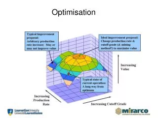
Evolutionary Structural Optimisation. KKT Conditions for Topology Optimisation. KKT Conditions (cont’d). KKT Conditions (cont’d). Strain energy density should be constant throughout the design domain This condition is true if strain energy density is evenly distributed in a design.

E N D
KKT Conditions (cont’d) • Strain energy density should be constant throughout the design domain • This condition is true if strain energy density is evenly distributed in a design. • Similar to fully-stressed design. • Need to compute strain energy density Finite Element Analysis
Evolutionary Structural Optimisation (ESO) • Fully-stressed design – von Mises stress as design sensitivity. • Total strain energy = hydrostatic + deviatoric (deviatoric component usually dominant in most continuum) • Von Mises stress represents the deviatoric component of strain energy. • Removes low stress material and adds material around high stress regions descent method • Design variables: finite elements (binary discrete) • High computational cost. • Other design requirements can been incorporated by replacing von Mises stress with other design sensitivities – 0th order method.
ESO Algorithm • Define the maximum design domain, loads and boundary conditions. • Define evolutionary rate, ER, e.g. ER = 0.01. • Discretise the design domain by generating finite element mesh. • Finite element analysis. • Remove low stress elements, • Continue removing material until a fully stressed design is achieved • Examine the evolutionary history and select an optimum topology that satisfy all the design criteria.
Fixed ESO solution Cherry Gravitational Load Initial design domain
Load Case 1: 2N/mm Roller support Fixed support Load Case 2: 2N/mm 2.5D Optimisation • Reducing thickness relative to sensitivity values rather than removing/adding the whole thickness Non-Design Domain Mesh Size 14436, less the 268 elements removed from mouth of spanner
720 477 24 Uniform Temperature P Thermoelastic problems • Both temperature and mechanical loadings • FE Heat Analysis to determine the temperature distribution • Thermoelastic FEA to determine stress distribution due to temperature • Then ESO using these stress values Design Domain
Group ESO • Group a set of finite elements • Modification is applied to the entire set • Applicable to configuration optimisation
P P Multiple Criteria • Using weighted average of sensitivities as removal/addition criteria Maximise first mode frequency & Minimise mean compliance AR 1.5 Mesh 45 x 30
Optimum Solutions (70% volume) wstiff:wfreq = 1.0:0.0 wstiff:wfreq = 0.7:0.3 wstiff:wfreq = 0.5:0.5 wstiff:wfreq = 0.3:0.7 wstiff:wfreq = 0.0:1.0
Chequerboard Formation • Numerical instability due to discretisation. • Closely linked to mesh dependency. • Piecewise linear displacement field vs. piecewise constant design update
Smooth boundary: Level-set function • Topology optimisation based on moving smooth boundary • Smooth boundary is represented by level-set function • Level-set function is good at merging boundaries and guarantees realistic structures • Artificially high sensitivities at nodes are reduced, and piecewise linear update numerically more stable • Manipulate G implicitly through f http://en.wikipedia.org/wiki/File:Level_set_method.jpg
Topology Optimisation using Level-Set Function • Design update is achieved by moving the boundary points based on their sensitivities • Normal velocity of the boundary points are proportional to the sensitivities (ESO concept) • Move inwards to remove material if sensitivities are low • Move outwards to add material if sensitivities are high • Move limit is usually imposed (within an element size) to ensure stability of algorithm • Holes are usually inserted where sensitivities are low (often by using topological derivatives, proportional to strain energy) • Iteration continued until near constant strain energy/stress is reached.