Download
1 / 40
400 likes | 411 Views
Understand the dynamics of single-cylinder engines, balancing revolving and reciprocating masses, and mitigating inertia forces for better performance. Learn effective techniques for balancing forces on the engine frame and main pin at different crank rotations.

E N D
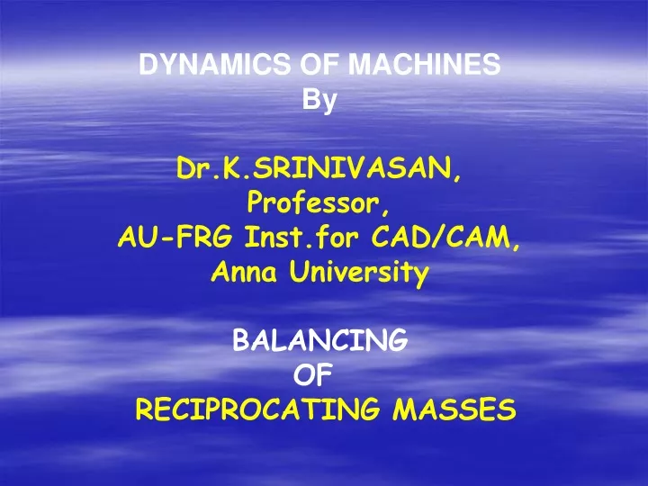
DYNAMICS OF MACHINES By Dr.K.SRINIVASAN, Professor, AU-FRG Inst.for CAD/CAM, Anna University BALANCING OF RECIPROCATING MASSES
SINGLE CYLINDER ENGINE • IN-LINE ENGINES- • 3 , 4 ,5, 6 cylinders are Common • V-ENGINES – 4, 6, 8,10, 12 ,16 with 6 & 8 being popular • RADIAL ENGINES-
6-cylinder inline engine Crank arrangement
Effect of Inertia forces in a SINGLE CYLINDER ENGINE: mA r 2 –due to rotating part y A 2 3 θ 4 B O2 m BA B x 1 Cylinder wall main bearing mA r 2 –inertia force due to revolving masses [mB r2 (cos θ+ cos 2 θ/ n + ……. )] -inertia force due to reciprocating masses
F23 F32 3 Tg F21 F43 F12 F41 Shaking force, F x21 = m B AB Shaking couple , T = x F41
Forces on the frame of the engine Shaking force, F x21 = m B A B Shaking couple , T = x F41
shaking force Forces of shaking couple Shaking force, F x21 = m B AB Shaking couple , T = x F41
y A 2 3 F21y F21 4 B θ=t x O2 F21x 1 F 14 main bearing F21x– unbalanced inertia force along the line of stroke F21y& F 14 - unbalanced couple on the engine cylinder
unbalanced force, F x21 = m B AB = mB {r2 (cos θ+ cos 2 θ/ n + ……. )} = mB {r2 cos θ} + mB r2 {cos 2 θ/ n } unbalanced couple , T = x F41 = x F y21 Primary disturbing force secondary disturbing force
m A r 2 Fy piston inertia force F21 Fx Fx= F x21 + m A r 2cosωt = mB r2 {cos ωt+ cos 2 ωt / n} + m A r 2cosωt Fy = m A r 2sinωt Can be fully balanced (due to rotating masses)
m A Secondary Imaginary crank mB= piston mass mB 3 2 2 4 r/4n θ=t x O2 F21x B 1 m A- mass at crank radius representing revolving masses of the crank shaft m B- imaginary mass at crank radius equal to reciprocating masses F x21 = mB r2 {cos ωt}+ mB r2 {cos 2 ωt / n}
mB r2 mB balancing force 2 θ=t b B r B 2 cos ωt mB r2cos ωt 1 Primary disturbing force b B r B 2 b B r B 2 sin ωt this force to line stoke not balanced b B r B= mB r for 100 %Balancing along the line of stroke
Example : • Data given : • Engine : Single cylinder oil engine • Stroke : 375 mm • speed : 300 rpm • Mass of the reciprocating parts : 68 kg • Revolving parts : 81.5 kg at crank radius • Radius at which balance • mass to be introduced at 180 o : 150 mm • Nature of balancing to be obtained : wholeof the revolving parts • & • one-half of the reciprocating parts • To find : 1. required balancing mass • 2. Residual unbalanced force on the main bearing
Solution : • The total equivalent revolving mass at • crank radius which has to be balanced = 81.5 + 68 X 0.5 • = 115.5 kg • @ (375/2) mm radius • We have. M b X r b = 115.5 X (375 /2) • Where M b is the balancing mass • & r b is radius of the balancing mass • Balancing mass @ 150 mm radius = 115.5 X (375 /2) / 150 = 144.375 kg Contd..
Calculation of residual unbalancedforce : = (2 X X 300 ) /60 =31.4 rad /s Unbalanced force parallel to theline of line of stroke ( due to reciprocating mass) F parallel= [ ½ X {68 2 r cos }] Unbalanced force perpendicular to the line of line of stroke ( due to reciprocating mass) F perpendicular = [ ½ X {68 2 r sin }] Total unbalanced force ,F = ½ X 68 2 r = ½ X 68 X 31.4 2 X 0.1875 = 6,286 N
Balancing web
Engine specifications: • one - cylinder • four - stroke • Bore : 75 mm • Stroke : 88.5 mm • l/ r : 3.5 • rpm : 3400 • m A : 5 kg • m B :2.1 kg
=43.2 k N Variation of unbalanced force with crank rotation
Engine fully balanced for revolving masses and Unbalanced for reciprocating masses
(4.27 kg at 44 mm) =14.9 kN Unbalanced force on the engine with exact balancing
Partially balanced for reciprocating masses
(6.4 kg at 44 mm) =7.5 kN unbalanced force on the engine with over balancing
=14.9 k N =43.2 k N Speed 3400 rpm 30o- 40o =12.75 k N Forces on the main pin at various balancing conditions
Effect of crank balancing on the shaking force Unbalanced Exact balancing overbalanced Unbalanced Exact balancing overbalanced
Extended con.rod Beyond crankpin
MULTI CYLINDER IN-LINE ENGINES: • Commoncrank shaft • driven by number of connecting rods • Angular interval between successive cranks , • (2 / n) in the case of 2-stroke engine • (4 / n) in the case of 4-stroke engine • Where ‘n’ is the number of cylinders • firing order influences balancing condition
Effect of unbalanced inertia forces due to reciprocating masses: Line of stroke Couple effect
Condition for complete balance of primary disturbing forces In a multi cylinder in line engines Q Line of stroke Line of stroke b g a f h c e o d 1 2 Q’ 3 4 m l n s r P End view of the cranks Line of stroke rotated