Download
1 / 45
490 likes | 1.04k Views
Small Gas Engines. Chapter 14. Overview. Identify differences between internal and external combustion engines Understand 2-stroke vs. 4-stroke engines Understand subsystems of small gas engines Discuss procedures for assembling and disassembling small gas engines.

E N D
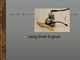
Small Gas Engines Chapter 14
Overview • Identify differences between internal and external combustion engines • Understand 2-stroke vs. 4-stroke engines • Understand subsystems of small gas engines • Discuss procedures for assembling and disassembling small gas engines
Internal Combustion Engines (ICE) vs.External Combustion Engines (ECE) • External combustion engines: produce heat outside of the cylinder containing the piston • Often used boilers to create steam • Internal combustion engines: produce heat Inside of the cylinder containing the piston • More reliable than ECE • Produce more power than similar size ECE • Used to power MOST vehicles in the USA • Used in agriculture and construction industries
Continued… • Cylinder ( aka. cylinder bore): is a hole in the block that directs the piston during movement • The ICE began replacing the ECE about 100 years ago.
Engine Theory • All ICEs convert chemical energy into mechanical power and share common mechanical elements • Two main types of engines • Two Stroke • Four Stroke
4-Stroke Engine • Can be any number of cylinders (1,2,3,4,6,8,10,12) and all are coupled to a single crank-shaft • Crank-shaft: converts the reciprocal motion of the pistons into rotary motion and powers the load • Piston: a cylindrical engine component that slides back and forth in the cylinder when propelled by the force of combustion.
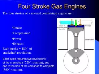
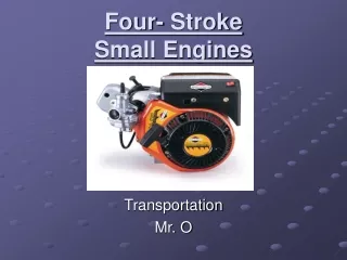
4-Stroke Engine (continued) • Stroke: the movement of the piston from the bottom limit of its travel to the top limit of its travel in the cylinder bore. • Require 4 strokes of the piston to complete one cycle • Intake Stroke • Compression Stroke • Power Stroke (combustion) • Exhaust Stroke
4-Stroke Engines Intake Power Exhaust Compression
4-Stroke Engine (1-INTAKE) • Intake Stroke: (downward) creates a partial vacuum drawing air into the cylinder through the carburetor where liquid fuel is atomized and mixed with the air (called a fuel-air charge). • Intake valve is open • Exhaust valve is closed 4-stroke graphic
4-Stroke Engine (2-Compression) • Compression Stroke: (upward) Fuel-air charge is squeezed to about 1/10th of its original volume • Bottom Dead Center (BDC) when the piston is at its lowest point (crankshaft is rounding the bottom of its travel) • Top Dead Center (TDC) when the piston is at its highest point (crankshaft is rounding the top of its travel) • Compression ratio is mathematical relationship between BDC and TDC (ie: 10:1 compression) • Intake and exhaust valves are closed 4-stroke graphic
4-Stroke Engine (3-Power) • Power Stroke: (downward) With piston near TDC the compressed fuel-air charge is detonated (by the spark plug) • Combusting gasses expand pushing down piston. • The connecting rod pushes down on the crank shaft causing it to rotate • Intake and exhaust valves are closed 4-stroke graphic
4-Stroke Engine (4-Exhaust) • Exhaust: (upward) Piston moves from BDC to TDC pushing the spent fuel-air mixture out of the cylinder • Piston is moved up by momentum or by power stroke of another piston pushing on the crank shaft • Intake valve is closed • Exhaust valves is open 4-stroke graphic
4-Stroke Engine Animation http://upload.wikimedia.org/wikipedia/commons/a/a6/4-Stroke-Engine.gif
2-Stroke Engine • Every upward stroke is a compression stroke • Every downward stroke is a power stroke • Intake and Exhaust stroke occur during the compression and power strokes • Every revolution of the crankshaft produces power • On a 4-stroke engine, it takes 2 revolutions
2-Stroke Engines (Advantages) • 2-stroke engines are more powerful for their size • Good at high RPM (revolutions per minute) applications • Simpler design than 4-stroke (less parts) • No valve train • No cam-shaft • Lighter than 4-stroke engines of comprable power • No oil reservoir • No valve train, cam, etc. • Can be operated at any angle (no oil reservoir)
2-Stroke Engines • Intake and exhaust occur through ports on the side of the cylinder. • Oil is mixed with the fuel and burned in the combustion chamber. • Pressure from the moving piston pushes gas/air/oil where it needs to go.
2-Stroke Engine (disadvantages) • Exhaust is dirtier than 4-stroke because oil is burned • They wear more quickly than 4-stroke because every other stroke is a power stroke • They don’t last as long • Mixing oil with fuel is inconvenient and if forgotten it will destroy the engine
2-Stroke Engine Animations • http://www.animatedengines.com/twostroke.html • http://fr.wikipedia.org/wiki/Fichier:2-Stroke_Engine_ani.gif
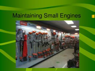
Engine Subsystems • Many of them on all engines • All must perform properly for peak performance • Cooling subsystem • Electrical subsystem • Lubrication subsystem • Mechanical subsystem • Governing subsystem • Fuel subsystem
Cooling Subsystem • Can be cooled by air or liquid • Air cooled systems • Cooling fins increase surface area • Flywheel blades direct air across engine fins • Sheet metal shrouds direct the air • Liquid cooled systems • Water jackets surround cylinder walls • Water pumps move water through jackets to radiator • Radiator expose surface area to surrounding air • Thermostat allows/impedes flow of water to radiator
Lubrication Subsystem • Oil distribution mechanism • Oil seals • Piston rings • Oil
Lubrication Subsystem • ALL moving parts must be lubricated • Splash lubrication method • Better for small gas engines • “Oil dipper” attached to bottom of connecting rod flings oil up on bottom of pistons • Piston Rings • Oil ring: (bottom ring) limits the amount of oil that squeezes past the piston into the combustion chamber • Compression ring(s): (upper ring(s)) contain combustion, scrape oil off of cyl. walls back into crankcase.
Lubrication Subsystem • Oil • Protects internal parts from corrosion • Cleans engine for foreign matter and allowing it to settle into the oil reservoir (crankcase or oil pan) • Seal the engine by filling small spaces between moving parts (ie: piston rings and moving parts) • Cushion moving parts from the power stroke • Improve fuel economy by reducing friction • Viscosity: measures resistance to flow (thickness) • Developed by the • Society of Automotive Engineers (SAE)
Mechanical Subsystem • Converts the force of the expanding gasses during combustion into mechanical power and delivers it to the crankshaft • Engine block (housing for all components) • Piston • Piston pin (aka: Wrist pin) • Connecting rod • Crankshaft (crankpin journal) • In a 4-stroke engine the crankshaft also powers the camshaft and valvetrain.
Mechanical Subsystem: Camshaft • Opens and closes valves by pushing on rods called lifters (some are adjustable for cam wear)
Mechanical Subsystem: Flywheel • Heavy metal disk attached to the Crankshaft • Inertia of the rotating engine created by power stroke helps the engine coast through the exhaust, intake and compression stroke • Smoothes out the power produced by the engine so it does not continually speed up and slow down
Mechanical Subsystem • This system takes the most wear (usually not visible) • Measurements are made in critical areas for wear and for warpage • Micrometers • Feeler gauges (AKA: thickness Gauge)
Electrical Subsystem • Produces the current that fires the sparkplug • Permanent magnet in the flywheel • Magnet passes the armature as flywheel spins creating low voltage • Converted to high voltage in the ignition coil • Spark jumps the gap in the spark plug to ignite fuel/air charge
Electrical Subsystem • Timing • Shear pin (key) keeps flywheel aligned on the crankshaft so spark is produced before TDC • Spacing of armature • Too close will rub on flywheel • Too far produces weak spark • Sparkplug • Must be “gapped” properly using feeler guage
Governing and Fuel Subsystem • Work in conjunction with one another • Governing system is designed to keep the engine running at the desired speed regardless of load • Fuel subsystem is responsible for creating the fuel/air mix used to power the engine and deliver it to the combustion chamber • Carburetor • Fuel injectors
Fuel Injected System • Fuel is pressurized and sprayed into the cylinder before TDC • Very common on cars and trucks with gas or diesel engines • Regulated by computers in modern cars to achieve maximum performance with minimum emissions
Carbureted System • Very common on small engines and older cars • Fuel vapor is drawn through the carb by the air that rushes past it (by the intake stroke) • This occurs in the venturi. • Venturi Effect states that pressure decreases as velocity increases.
Governing System Definitions • Venturi: Narrow restricting section of carburetor where air speeds up and drafts the fuel vapor along with it into Cylinder • Choke: Plate-like device (usually) that varies the amount of air that can enter the carb. • Throttle: plate-like device located in back of venturi that regulates amount of fuel air mix entering the cylinders. • Load: condition under which an engine runs when it does work • Choke plate and Throttle are open
Governing System Definitions • Idle: the condition an engine will run under when it is warmed up to temperature and NOT under load • Choke is open • Throttle is closed • Idle Bypass Circuit: small passageway that allows some air/fuel mix to escape around the throttle plate to keep engine running
Measuring, Testing and Troubleshooting • All complex machines need maintenance, periodic testing and troubleshooting to run their best • Emissions testing • Temperature regulation • Tune-ups • Air filter changes • Oil changes • Etc.
Efficiency • Volumetric Efficiency: measures how well the engine “breathes.” Measure of how much fuel air mixture is drawn into cylinders with the amount that could be drawn in. • Mechanical efficiency: Percentage of power developed in the cylinder compared to the power that is actually delivered to the crankshaft
Efficiency • Thermal Efficiency: (aka heat efficiency) measure of how much heat is actually used to drive the pistons downward. • Only about 25% is used to drive the piston downward, the rest is lost. • Practical Efficiency: simple measure of how efficiently an engine uses its fuel supply • If used for motive power it is measured in MPG • Takes into account all losses of efficiency • friction • Drag • Thermal loss, etc
Horsepower • Developed as a means of comparing the power produced by James Watt’s steam engine to the amount of work a horse could do. • 550 foot-pounds per second • Horsepower capability is affected by • Bore: diameter of the piston • Stroke: Distance from TDC to BDC • Frictional loss: within the engine (frictional vs non-frictional bearings)
Horsepower Terminology • Brake Horsepower (bhp): the hp available for use at the crankshaft. Increases with engine rpm then decrease when engine is revved to high • Indicated horsepower (ihp): Theoretical term. Measure of the power developed by the fuel air charge upon ignition
Horsepower Terminology • Frictional Horsepower (fhp): represents the part of the potential hp lost due to friction within the engine ihp-bhp=fhp • Rated horsepower (rhp): usually represents about 80% of the engines bhpbecause engines should not be run at full capability all the time (the sticker rating)