Download
1 / 52
520 likes | 668 Views
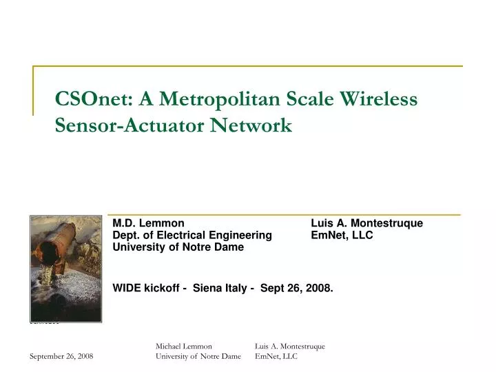
CSOnet: A Metropolitan Scale Wireless Sensor-Actuator Network. M.D. Lemmon Luis A. Montestruque Dept. of Electrical Engineering EmNet, LLC University of Notre Dame WIDE kickoff - Siena Italy - Sept 26, 2008. Outline. Combined Sewer Overflow Problem In-line Storage using CSOnet

E N D
CSOnet: A Metropolitan Scale Wireless Sensor-Actuator Network M.D. Lemmon Luis A. MontestruqueDept. of Electrical Engineering EmNet, LLCUniversity of Notre Dame WIDE kickoff - Siena Italy - Sept 26, 2008. Michael Lemmon Luis A. MontestruqueUniversity of Notre Dame EmNet, LLC
Outline • Combined Sewer Overflow Problem • In-line Storage using CSOnet • CSOnet System Hardware • CSOnet Middleware • Real-time Control Strategy • Future Directions Michael Lemmon Luis A. MontestruqueDept. of Electrical Engineering EmNet, LLCUniversity of Notre Dame
CSOnet concept: use of wireless sensor-actuator networks for distributed monitoring and control of combined sewer overflow (CSO) events. Concept originally created at Notre Dame (Lemmon/Talley) Funded through the State of Indiana’s 21st Century Technology Fund1 million USD (2004-2006) - 1 million USD (2007-2009) Academic, private sector, and public sector partners 150+ Sensor network monitoring 13,000 acres (summer 2008) Actuation component scheduled for completion in summer 2009 Purdue(Bagchi/Chappell) City of South Bend EmNet LLC(L. Montestruque) Greeley & Hansen Notre Dame(Lemmon/Talley) CSOnet Project Background 3 Michael Lemmon Luis A. MontestruqueDept. of Electrical Engineering EmNet, LLCUniversity of Notre Dame
Dry Weather Wet Weather Overflow Combined Sewer Overflow During Wet Weather South Bend Wastewater Treatment Plant St. Joseph River Combined Sewer Overflow Events • Combined sewer overflow (CSO) events occur when a municipality dumps untreated water from combined storm and sanitary sewer flows into a river/stream. • “Such ‘exceedances’ can pose risk to human health, threaten aquatic life and its habitat, and impair the use and enjoyment of the Nation’s waterways.” • EPA fines for CSO events- 1994 CSO Control Act- Fines are Significant • Problem is Large-scaleOver 772 cities nationwide Interceptor Sewer EPA, “Combined Sewer Overflow Control Policy,” April 19, 1994. (www.epa.gov) Michael Lemmon Luis A. MontestruqueDept. of Electrical Engineering EmNet, LLCUniversity of Notre Dame
Combined Sewer Overflow Events Michael Lemmon Luis A. MontestruqueDept. of Electrical Engineering EmNet, LLCUniversity of Notre Dame
Combined Sewer Overflow Events Michael Lemmon Luis A. MontestruqueDept. of Electrical Engineering EmNet, LLCUniversity of Notre Dame
Solution Strategies Off-line Storage TunnelsChicago’s TARP project Sewer Separation Expansion of WWTP These strategies all require significant investment in new infrastructure Michael Lemmon Luis A. MontestruqueDept. of Electrical Engineering EmNet, LLCUniversity of Notre Dame
In-line Storage • Store excess water in unused parts of the system • Reduces need for infrastructure enhancement • Requires real-time monitoring and control of flows Reduced inflow to Manhole Ballows us to increase inflow through Manhole A Inflow of Storm Water conduit conduit conduit Manhole A Manhole B Michael Lemmon Luis A. MontestruqueDept. of Electrical Engineering EmNet, LLCUniversity of Notre Dame
Combined Sewer Trunk Lines RetentionBasin RetentionBasin RetentionBasin City Engineer RetentionBasin CSO DiversionStructure Interceptor Sewer Line Outfallto River Outfallto River Outfallto River Outfallto River Centralized Model Predictive Control • Interceptor Sewer to Wastewater Treatment Plant • Monitoring and Control over SCADA network • Pre-1974 combined sewer trunklines Michael Lemmon Luis A. MontestruqueDept. of Electrical Engineering EmNet, LLCUniversity of Notre Dame
SCADA Systems • Expensive • Limited implementation • Limited feedback data • High reliance on hydraulic models Michael Lemmon Luis A. MontestruqueDept. of Electrical Engineering EmNet, LLCUniversity of Notre Dame
INTERNET City Engineer Distributed In-line Storage • Distributed Feedback Control of In-line Storagesets up interacting “control zones” • Gateways connect to Internet to provideglobal monitoring of system Michael Lemmon Luis A. MontestruqueDept. of Electrical Engineering EmNet, LLCUniversity of Notre Dame
Distributed In-line Storage Michael Lemmon Luis A. MontestruqueDept. of Electrical Engineering EmNet, LLCUniversity of Notre Dame
R R I R R R R R I I Ireland/Miami Network (Summer 2005) Prototype system controls retention basin based on flow measurements at CSO 22 diversion structure • 7 Relay Rnodes (radios) • 3 Instrumentation Inodes (sensors) • 1 Gateway Gnode connect to the internet • Automated valve • Network is fully deployed and operational CSO 22Diversion Point R Combined SewerTrunk Line I G V G V Retention Basin First month of service the system prevented 2 million gallon CSO discharge Continuous operation since summer 2005. CSO22Area Michael Lemmon Luis A. MontestruqueDept. of Electrical Engineering EmNet, LLCUniversity of Notre Dame
South Bend CSOnet PHASE 1: (summer 2008) 800 km of sewers 50 km2 of CSO area 110 sensors Monitor 36 outfalls, 27 interceptor locations, 42 trunkline locations, and 5 basins PHASE 2: (summer 2009) Control at least 18 outfalls Control storage in retention basins 14 Michael Lemmon Luis A. MontestruqueDept. of Electrical Engineering EmNet, LLCUniversity of Notre Dame
CSOnet Website Overflow Event Sensor Location Michael Lemmon Luis A. MontestruqueDept. of Electrical Engineering EmNet, LLCUniversity of Notre Dame
Outline • Combined Sewer Overflow Problem • In-line Storage using CSOnet • CSOnet System Hardware • CSOnet Middleware • Real-time Control Strategy • Future Directions Michael Lemmon Luis A. MontestruqueDept. of Electrical Engineering EmNet, LLCUniversity of Notre Dame
CSOnet Architecture • Hierarchical network • Unicasts in low level subnets, Multicasts over higher level • 3 types of Nodes - Gnode, Rnode, Inode Michael Lemmon Luis A. MontestruqueDept. of Electrical Engineering EmNet, LLCUniversity of Notre Dame
CSOnet Inode Emplacement Rnode To next Rnode Stoplight Pole Manhole Cover Antenna Inode microprocessor Stilling Well Sensor Michael LemmonDept. of Electrical EngineeringUniversity of Notre Dame Slide provided by courtesy of EmNet LLC
Actuators GNode Cabinet or Traffic Signal Manhole Cover Antenna Conduit INode Overflow Line Stilling Well Actuated Valve Stilling Well Combined Sewer Trunkline Weir Larger Parallel Throttle Line Sensor Interceptor Line Sensor Actuated Valve Pneumatic Bladder Slide provided by courtesy of EmNet LLC Michael LemmonDept. of Electrical EngineeringUniversity of Notre Dame
Composite Manhole Cover • Manhole is extremely corrosive environment • Initial prototypes “rusted” away with a few months • Integration of processor, radio transceiver, and antenna into manhole cover • William Chappell - Purdue Michael Lemmon Luis A. MontestruqueDept. of Electrical Engineering EmNet, LLCUniversity of Notre Dame
Intelligent Radio Antenna • Municipal deployments must cope with fading effects due to multipath interference. • Intelligent switching between multiple antennae single directional antenna Intelligentswitching antenna Ideal Antenna withangular diversity Slide provided by courtesy of Bill Chappell (Purdue) Michael Lemmon Luis A. MontestruqueDept. of Electrical Engineering EmNet, LLCUniversity of Notre Dame
Chasqui Module • Inode and Rnode are based on the Chasqui Module Chasqui 2.0 with antenna Chasqui 1.0 Chasqui 1.1 Chasqui 2.0 • Based on UCB Mica2 Module • MaxStream Radio (115 kbps/900 MHz) • Rugged Sensor-Actuator I/F • Precision Real-time Clock (2ppm drift) • TinyOS Compatible Michael Lemmon Luis A. MontestruqueDept. of Electrical Engineering EmNet, LLCUniversity of Notre Dame
GNode • Gateway Node consists of • Single Board Computer (SBC) xx86- compact Linux • Chasqui Node (radio - actuator interface) • Cellular connectivity to Internet. Single Board Computer Michael Lemmon Luis A. MontestruqueDept. of Electrical Engineering EmNet, LLCUniversity of Notre Dame
Outline • Combined Sewer Overflow Problem • In-line Storage using CSOnet • CSOnet System Hardware • CSOnet Middleware • Real-time Control Strategy • Future Directions Michael Lemmon Luis A. MontestruqueDept. of Electrical Engineering EmNet, LLCUniversity of Notre Dame
Network Reply to Request Request for Data Type Middleware for Mesh Radio Networks • Middleware maintains an network abstraction that can be easily used by application software • Time-slotted publish-subscribe network abstraction • Middleware services • Clock Synchronization • Networking Service • Routing Service • Power Management Service • Reprogramming Service • Programmed using TinyOS Data Sources Data Sink Michael Lemmon Luis A. MontestruqueDept. of Electrical Engineering EmNet, LLCUniversity of Notre Dame
Networking Service 2 2 3 2 2 3 2 2 1 1 1 1 1 1 3 3 1 1 1 SINK SINK SINK 2 2 SINK 2 2 1 1 1 1 1 1 1 1 2 1 2 • Network service uses directed flooding to create a gradient table 26 Michael Lemmon Luis A. MontestruqueDept. of Electrical Engineering EmNet, LLCUniversity of Notre Dame
Stateless Gradient-based Routing 2 2 2 2 2 2 2 2 3 3 3 3 3 3 3 3 2 2 2 2 1 1 1 1 1 1 1 1 3 3 3 3 1 1 1 1 3 3 3 3 SINK SINK SINK SINK 2 2 2 2 2 2 2 2 1 1 1 1 1 1 1 1 1 1 1 1 2 2 2 2 • Broadcast to all upgradient nodes 27 Michael Lemmon Luis A. MontestruqueDept. of Electrical Engineering EmNet, LLCUniversity of Notre Dame
Congestion Issues Subnet 23 Throughput Results • CSOnet has two types of subnets- large diameter with few sensors- small diameter with many sensors • Small diameter networks can have congestion problems unless the data received at the gateway is buffered Michael Lemmon Luis A. MontestruqueDept. of Electrical Engineering EmNet, LLCUniversity of Notre Dame
Power Management Management of system duty cycle 2 percent duty cycle - 5 minute period During sleep cycle, microprocessor put into deep sleep mode. External timer is used to wake the system back up Requires tight “clock” synchronization Chasqui uses Dallas DS3231 RTC with 2 ppm drift. Resync network clocks every six hours Chasqui service lifetime 2 years between service 3.6 volt - 19 amp-hour lithium source Currently more cost effective to replace batteries than to use renewable power systems such as solar. ON ON ON ON ASLEEP ASLEEP ASLEEP 29 Michael Lemmon Luis A. MontestruqueDept. of Electrical Engineering EmNet, LLCUniversity of Notre Dame
Wireless Reprogramming • “Stream” Reprogramming protocol developed by Dr Saurabh Bagchi (Purdue) • Less overhead than Deluge • Stream segments the program image into Stream-RS (Stream Reprogramming Support) and Stream-AS (Stream Application Support) • Stream-RS • Core reprogramming component • Preinstalled, before deployment, in all nodes • Stream-AS • A small subset of reprogramming component that is attached to the user application • Instead of wirelessly transferring through the network user application plus the entire reprogramming component, Stream transfers Stream-AS plus the user application Flash Program memory Stream-RS (Image-0) Currently executing program Stream-AS + User application (Image-1) Unused portion Slide provided by ourtesy of Saurabh Bagchi (Purdue) Michael Lemmon Luis A. MontestruqueDept. of Electrical Engineering EmNet, LLCUniversity of Notre Dame
Outline • Combined Sewer Overflow Problem • In-line Storage using CSOnet • CSOnet System Hardware • CSOnet Middleware • Real-time Control Strategy • Future Directions Michael Lemmon Luis A. MontestruqueDept. of Electrical Engineering EmNet, LLCUniversity of Notre Dame
Q = flow rate (m3/s) A = cross section area of flow (m2) H = head level (m) ground level H=0 Complete Dynamic Wave Model • Momentum Equation • Continuity Equation • Manning’s equation Michael Lemmon Luis A. MontestruqueDept. of Electrical Engineering EmNet, LLCUniversity of Notre Dame
wu Qu wd Q Hu manhole Hd Flow, Q pipe Hu L Hd Ground H=0 Simplified Wave Model • Flow Resistance Equation(momentum equation) • Simplified Continuity Equation Where ai= water surface area Michael Lemmon Luis A. MontestruqueDept. of Electrical Engineering EmNet, LLCUniversity of Notre Dame
Distributed Real-time Control • Model Variables • wi = storm inflow • Oi = overflow • ui = diverted flow • Hi = water height (head) • Q I = pipe flow rate Optimal Control Problem • Maximize “diverted flow” • Subject to: • Conservation of Mass • Conservation of Momentum • Admissible control • No flooding • WWTP capacity limit Michael Lemmon Luis A. MontestruqueDept. of Electrical Engineering EmNet, LLCUniversity of Notre Dame
Supervisory Control Strategy Control Selection Algorithm • Assume costs are ordered as • If node ij is flooded • If node ijis not flooded then : active flood constraint Michael Lemmon Luis A. MontestruqueDept. of Electrical Engineering EmNet, LLCUniversity of Notre Dame
Supervisory Control Results • “Optimal” Supervisory Control Strategy • Open valves until “flooding” constraint is active • Then reduce diverted inflow to prevent violation of flooding constraint Table A. Scenario A—Moving Uniform Rainfall Michael Lemmon Luis A. MontestruqueDept. of Electrical Engineering EmNet, LLCUniversity of Notre Dame
STORM FLOW VALVE OVERFLOW INODE Pressure Sensor(water height) Pressure-based Feedback • Actual system only has “pressure” (head) measurements • Decentralized Pressure-based Controller used to enforce flooding constraint. • Model of Head Level Dynamics • Limitation: the diverted flow must be positive FLOODING CONSTRAINT ACTIVE HEIGHT TIME Michael Lemmon Luis A. MontestruqueDept. of Electrical Engineering EmNet, LLCUniversity of Notre Dame
Input-Output Behavior of Node • Testbed Experiments showed that “head” level dynamics had at least 3 state variables • Head level, downstream flow rate, water stored in upstream link Ellipsoidal shape of response implies additional energy storage Michael Lemmon Luis A. MontestruqueDept. of Electrical Engineering EmNet, LLCUniversity of Notre Dame
Head Model Identification • Drive interceptor line with a “persistently exciting” input signal • Gather input/output data for a “design” set and a “test” set. • Use “design” data set and Matlab’s SysID toolbox to identify a state-based model • Test that model against the “test” data set. SB Interceptor Line Node 8 Model Michael Lemmon Luis A. MontestruqueDept. of Electrical Engineering EmNet, LLCUniversity of Notre Dame
Pressure-based Controller Design Controller • Disturbance rejection problem • Loopshaping Design • Often yields PID-type control • State-based controller PLANT Reference pressure NODE 8”s RESPONSE Loopshaping Design Plot Michael Lemmon Luis A. MontestruqueDept. of Electrical Engineering EmNet, LLCUniversity of Notre Dame
Flooding under Supervisory Control • Supervisory strategy is only “necessary” for optimality • This strategy can lead to localized flooding in a flooded node loses “control authority” Michael Lemmon Luis A. MontestruqueDept. of Electrical Engineering EmNet, LLCUniversity of Notre Dame
Flood Prevention • Flooding may occur if node loses “control authority” • Flood Prevention Protocol • If node i is about to flood and has no remaining control authority THEN request upstream node to “hold” at its current head level. pipe Hu Hd Michael Lemmon Luis A. MontestruqueDept. of Electrical Engineering EmNet, LLCUniversity of Notre Dame
Simulation Results - Head Levels Michael Lemmon Luis A. MontestruqueDept. of Electrical Engineering EmNet, LLCUniversity of Notre Dame
Simulation Results - Total Overflows (ft3) • 10-60 percent reduction in total overflow Michael Lemmon Luis A. MontestruqueDept. of Electrical Engineering EmNet, LLCUniversity of Notre Dame
Outline • Combined Sewer Overflow Problem • In-line Storage using CSOnet • CSOnet System Hardware • CSOnet Middleware • Real-time Control Strategy • Future Directions Michael Lemmon Luis A. MontestruqueDept. of Electrical Engineering EmNet, LLCUniversity of Notre Dame
STORM FLOW VALVE Head level informationfrom upstream anddownstream nodes OVERFLOW INODE Pressure Sensor(water height) Moving toward Distributed Local Control • CSOnet’s controller • High-level supervisor to enforce optimality • Low-level decentralized controllers to enforce safety (no flooding) • We could do better with “distributed” local controls Michael Lemmon Luis A. MontestruqueDept. of Electrical Engineering EmNet, LLCUniversity of Notre Dame
Need for Real-time Middleware • Distributed control requires hard/firm real-time message delivery • It may be possible to develop real-time middleware services in isolation, but real-time guarantees are quickly lost as additional services are added. • The lack of composable middleware services capable of providing end-to-end hard/firm real-time guarantees limits is an obstacle to the use of low-level distributed control. • Future work is moving in this direction • Additional CSOnet Developments • Deployment of Actuation in South Bend System (summer 2009) • Two additional Indiana cities are installing CSOnet • Monitoring and Control of Civil Infrastructure • Bridge monitoring • Leak detection in water distribution networks Michael Lemmon Luis A. MontestruqueDept. of Electrical Engineering EmNet, LLCUniversity of Notre Dame
CSOnet Additional Projects • Fort Wayne, IN • CSO real time monitoring • CSO control • In-line storage • Multiple Interceptors • Greenfield, IN • CSO real time monitoring • Infiltration localization • Hoboken, NJ • Feasibility study • Flood prevention (reversed flows) • Omaha, NE • Feasibility study • Forced main Michael Lemmon Luis A. MontestruqueDept. of Electrical Engineering EmNet, LLCUniversity of Notre Dame
Homeland Security: Air • Protection against release of chem-bio agents in urban environments • Goal: determine release point and plume expansion using embedded sensor network SF6 wireless sensor Michael Lemmon Luis A. MontestruqueDept. of Electrical Engineering EmNet, LLCUniversity of Notre Dame
Homeland Security: Water Turbidity Sensor • Rapid detection of variations of water quality in water distribution systems • Standard off-the-self sensors: • Temperature • pH • Turbidity • Conductivity • Dissolved Oxygen • Pressure Michael Lemmon Luis A. MontestruqueDept. of Electrical Engineering EmNet, LLCUniversity of Notre Dame