Download
1 / 12
410 likes | 1.44k Views
The MMC is 68.2 mm, the largest allowable diameter for the boss. The position tolerance is referenced at RFS since no modifier is present in the feature control frame. The position tolerance is 0.3mm, regardless of feature size.

E N D
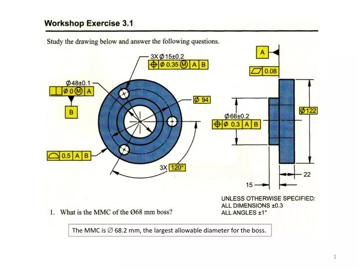
The MMC is 68.2 mm, the largest allowable diameter for the boss.
The position tolerance is referenced at RFS since no modifier is present in the feature control frame. The position tolerance is 0.3mm, regardless of feature size The MMC of the three holes is 14.8 mm, the smallest allowable diameter for the holes. The position tolerance for this case is 0.35 mm, the allowable tolerance at MMC. Since the size of the holes is 0.2 mm larger than MMC, the position tolerance is 0.55 mm. The perpendicularity tolerance for the three holes is 0.35 mm at MMC. The maximum perpendicularity tolerance for the three holes is 0.35 + 0.4 = 0.75 mm. No, this is a basic dimension and it does not have any tolerance associated with it.
Workshop Exercise 3.3- Solution 1. Establish the right face in the side view as datum feature A. Qualify this feature with a flatness of .005. 2. Establish the top surface in the front view as datum feature B. Qualify with a perp of .005 to datum feature A. 3. Establish the left surface in the front view as datum feature C. Qualify this with a perp of .005 to datum features A and B. 4. Establish all necessary dimensions as basic. 5. Position the .250 hole within a diameter of .005 RFS relative to datum features A, B, C. 6. Position the three holes within a diameter of .012 at MMC relative to datum features A,B,C. 7. In the front view, identify the upper right corner as point “Y” and the lower left corner as point “X”. Apply a profile tolerance of .020 between points X and Y relative to datum features A, B, C. . 3 8 1 3 X . 3 7 3 3 . 5 0 0 . 6 5 0 2 . 0 0 0 . 5 1 0 . 5 0 0 . 5 0 0 1 . 0 0 0 2 . 0 0 0 1 . 0 0 0 2 X R . 5 0 0 2 0 ° . 2 5 2 . 8 8 0 . 2 5 0 1 . 6 5 0 Side View Plan View 3.25
Workshop Exercise 3.3- Solution 1. Establish the right face in the side view as datum feature A. Qualify this feature with a flatness of .005. 2. Establish the top surface in the front view as datum feature B. Qualify with a perp of .005 to datum feature A. 3. Establish the left surface in the front view as datum feature C. Qualify this with a perp of .005 to datum features A and B. 4. Establish all necessary dimensions as basic. 5. Position the .250 hole within a diameter of .005 RFS relative to datum features A, B, C. 6. Position the three holes within a diameter of .012 at MMC relative to datum features A,B,C. 7. In the front view, identify the upper right corner as point “Y” and the lower left corner as point “X”. Apply a profile tolerance of .020 between points X and Y relative to datum features A, B, C. . 3 8 1 3 X . 3 7 3 3 . 5 0 0 . 6 5 0 2 . 0 0 0 . 5 1 0 . 5 0 0 . 5 0 0 1 . 0 0 0 2 . 0 0 0 1 . 0 0 0 2 X R . 5 0 0 2 0 ° . 2 5 2 . 8 8 0 . 0 0 5 . 2 5 0 1 . 6 5 0 A Side View Plan View 3.25
Workshop Exercise 3.3- Solution 1. Establish the right face in the side view as datum feature A. Qualify this feature with a flatness of .005. 2. Establish the top surface in the front view as datum feature B. Qualify with a perp of .005 to datum feature A. 3. Establish the left surface in the front view as datum feature C. Qualify this with a perp of .005 to datum features A and B. 4. Establish all necessary dimensions as basic. 5. Position the .250 hole within a diameter of .005 RFS relative to datum features A, B, C. 6. Position the three holes within a diameter of .012 at MMC relative to datum features A,B,C. 7. In the front view, identify the upper right corner as point “Y” and the lower left corner as point “X”. Apply a profile tolerance of .020 between points X and Y relative to datum features A, B, C. . 3 8 1 3 X . 3 7 3 3 . 5 0 0 . 6 5 0 2 . 0 0 0 . 5 1 0 . 5 0 0 . 0 0 5 A . 5 0 0 B 1 . 0 0 0 2 . 0 0 0 1 . 0 0 0 2 X R . 5 0 0 2 0 ° . 2 5 2 . 8 8 0 . 0 0 5 . 2 5 0 1 . 6 5 0 A Side View Plan View 3.25
Workshop Exercise 3.3- Solution 1. Establish the right face in the side view as datum feature A. Qualify this feature with a flatness of .005. 2. Establish the top surface in the front view as datum feature B. Qualify with a perp of .005 to datum feature A. 3. Establish the left surface in the front view as datum feature C. Qualify this with a perp of .005 to datum features A and B. 4. Establish all necessary dimensions as basic. 5. Position the .250 hole within a diameter of .005 RFS relative to datum features A, B, C. 6. Position the three holes within a diameter of .012 at MMC relative to datum features A,B,C. 7. In the front view, identify the upper right corner as point “Y” and the lower left corner as point “X”. Apply a profile tolerance of .020 between points X and Y relative to datum features A, B, C. . 3 8 1 3 X . 3 7 3 3 . 5 0 0 . 6 5 0 2 . 0 0 0 . 5 1 0 . 5 0 0 . 0 0 5 A . 5 0 0 B 1 . 0 0 0 2 . 0 0 0 1 . 0 0 0 2 X R . 5 0 0 2 0 ° . 2 5 2 . 8 8 0 . 0 0 5 . 2 5 0 1 . 6 5 0 A . 0 0 5 A B Side View Plan View 3.25 C
Workshop Exercise 3.3- Solution 1. Establish the right face in the side view as datum feature A. Qualify this feature with a flatness of .005. 2. Establish the top surface in the front view as datum feature B. Qualify with a perp of .005 to datum feature A. 3. Establish the left surface in the front view as datum feature C. Qualify this with a perp of .005 to datum features A and B. 4. Establish all necessary dimensions as basic. 5. Position the .250 hole within a diameter of .005 RFS relative to datum features A, B, C. 6. Position the three holes within a diameter of .012 at MMC relative to datum features A,B,C. 7. In the front view, identify the upper right corner as point “Y” and the lower left corner as point “X”. Apply a profile tolerance of .020 between points X and Y relative to datum features A, B, C. . 3 8 1 3 X . 3 7 3 3 . 5 0 0 . 6 5 0 2 . 0 0 0 . 5 1 0 . 5 0 0 . 0 0 5 A . 5 0 0 B 1 . 0 0 0 2 . 0 0 0 1 . 0 0 0 2 X R . 5 0 0 2 0 ° . 2 5 2 . 8 8 0 . 0 0 5 . 2 5 0 1 . 6 5 0 A . 0 0 5 A B Side View Plan View 3.25 C
Workshop Exercise 3.3- Solution 1. Establish the right face in the side view as datum feature A. Qualify this feature with a flatness of .005. 2. Establish the top surface in the front view as datum feature B. Qualify with a perp of .005 to datum feature A. 3. Establish the left surface in the front view as datum feature C. Qualify this with a perp of .005 to datum features A and B. 4. Establish all necessary dimensions as basic. 5. Position the .250 hole within a diameter of .005 RFS relative to datum features A, B, C. 6. Position the three holes within a diameter of .012 at MMC relative to datum features A,B,C. 7. In the front view, identify the upper right corner as point “Y” and the lower left corner as point “X”. Apply a profile tolerance of .020 between points X and Y relative to datum features A, B, C. . 3 8 1 3 X . 3 7 3 3 . 5 0 0 . 6 5 0 2 . 0 0 0 . 5 1 0 . 5 0 0 . 0 0 5 A . 5 0 0 B 1 . 0 0 0 2 . 0 0 0 1 . 0 0 0 2 X R . 5 0 0 2 0 ° . 2 5 2 . 8 8 0 . 0 0 5 . 2 5 0 . 0 0 5 A B C 1 . 6 5 0 A . 0 0 5 A B Side View Plan View 3.25 C
Workshop Exercise 3.3- Solution 1. Establish the right face in the side view as datum feature A. Qualify this feature with a flatness of .005. 2. Establish the top surface in the front view as datum feature B. Qualify with a perp of .005 to datum feature A. 3. Establish the left surface in the front view as datum feature C. Qualify this with a perp of .005 to datum features A and B. 4. Establish all necessary dimensions as basic. 5. Position the .250 hole within a diameter of .005 RFS relative to datum features A, B, C. 6. Position the three holes within a diameter of .012 at MMC relative to datum features A,B,C. 7. In the front view, identify the upper right corner as point “Y” and the lower left corner as point “X”. Apply a profile tolerance of .020 between points X and Y relative to datum features A, B, C. . 3 8 1 3 X . 3 7 3 3 . 5 0 0 M . 0 1 2 A B C . 6 5 0 2 . 0 0 0 . 5 1 0 . 5 0 0 . 0 0 5 A . 5 0 0 B 1 . 0 0 0 2 . 0 0 0 1 . 0 0 0 2 X R . 5 0 0 2 0 ° . 2 5 2 . 8 8 0 . 0 0 5 . 2 5 0 . 0 0 5 A B C 1 . 6 5 0 A . 0 0 5 A B Side View Plan View 3.25 C
Workshop Exercise 3.3- Solution 1. Establish the right face in the side view as datum feature A. Qualify this feature with a flatness of .005. 2. Establish the top surface in the front view as datum feature B. Qualify with a perp of .005 to datum feature A. 3. Establish the left surface in the front view as datum feature C. Qualify this with a perp of .005 to datum features A and B. 4. Establish all necessary dimensions as basic. 5. Position the .250 hole within a diameter of .005 RFS relative to datum features A, B, C. 6. Position the three holes within a diameter of .012 at MMC relative to datum features A,B,C. 7. In the front view, identify the upper right corner as point “Y” and the lower left corner as point “X”. Apply a profile tolerance of .020 between points X and Y relative to datum features A, B, C. . 3 8 1 3 X . 3 7 3 3 . 5 0 0 M . 0 1 2 A B C . 6 5 0 2 . 0 0 0 . 5 1 0 Y . 5 0 0 . 0 0 5 A . 5 0 0 B 1 . 0 0 0 2 . 0 0 0 1 . 0 0 0 2 X R . 5 0 0 2 0 ° . 0 2 0 A B C X Y X . 2 5 2 . 8 8 0 . 0 0 5 . 2 5 0 . 0 0 5 A B C 1 . 6 5 0 A . 0 0 5 A B 3.25 C