Download
1 / 16
160 likes | 199 Views
This study presents thorough thermal and structural analysis of a graphite beam dump with helium conduction, evaluating various scenarios to ensure safe operation under high energy deposition. Results provide insight into temperature distributions, stress levels, and displacement effects for reliable design optimization.

E N D
Beam Dump Design Dan Wilcox March 2012
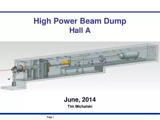
Overview Graphite Beam Dump 4m x 4m x 3.2m Helium Vessel + Iron Plates Upstream Iron Shield Outer Iron Shield Downstream Iron Shield
Energy deposition in beam dump has since increased to 780 kW This iron plate was removed Nikolas Vassilopoulos – NuFact 2011
Energy Deposition in Graphite Units W/m3
Thermal Analysis • Boundary condition: Two sides cooled to a constant 30°C. • Symmetry applied, one quarter modelled. • Mesh: quadratic hexahedral elements, maximum size 0.08m. • Properties based on graphite grade PSG-324, as used in the T2K beam dump. • The variation of thermal conductivity with temperature was taken into account. (To direction of extrusion)
Case 1: Solid Graphite Temperature in °C • Best case scenario, but impossible in practice • Results agree with hand calculation
Case 2: Graphite blocks, no heat transfer across gaps Temperature in °C • Worst case scenario for heat transfer • 0.4m x 0.4m extruded sections – similar to T2K
Case 3: Graphite blocks, helium conduction across gaps Temperature in °C • Assumed 2mm helium gaps – conservative • Assumed no convection – conservative
Structural Analysis • Sequential analysis – thermal then structural • Boundary condition: Each section was fully restrained at its outer face. • Loads: gravity, structural temperatures from thermal analysis • Symmetry applied, one quarter modelled. • The quadratic hexahedral thermal elements were converted to the equivalent structural elements. • The variation of mechanical properties with temperature was taken into account.
Stress Result – Von Mises Von Mises Stress in N/m2 • Maximum: 4.53MPa, occurring at the restraints • May be lower in practice due to deflection of restraints
Stress Result – 1st Principal 1st Principal Stress in N/m2 Von Mises Stress in N/m2 • Maximum tensile stress: 1.56MPa
Stress Result – 3rd Principal 3rd Principal Stress in N/m2 • Maximum compressive stress: 5.43MPa
Displacement Results X - Component Y - Component Maximum displacements; • δx; 3.3mm increase in length • δy; 0.63mm, -0.87mm • δz; 0.59mm, -0.80mm • Therefore no contact between adjacent blocks Z - Component
Failure Criteria Temperature • Rate of graphite oxidization increases with temperature. • Higher temperature means higher purity of helium required. • The limits set for T2K were; • 600degC: Helium should be < 30ppm O2, • 650degC: <10ppm O2 • (1 - 5% loss for 20yrs) Stress • Tensile tests were carried out at temperatures up to 900°C. • Tensile Strength: 7 - 8.5MPa (parallel), 4 - 5.5MPa (perpendicular) • Cf. Bending Strength: 14.7MPa (parallel), 9.8MPa (perpendicular) See “Status of the T2K Hadron Absorber Development - T.Ishida, 2006” for more details. (available online)
Conclusions • Max graphite temperature is expected to be somewhere between 425 and 575°C. • Based on T2K limits this is acceptable (Helium should be < 30ppm O2). • Graphite surface finish will have an important effect on heat transfer. • Tensile stress is not expected to exceed 1.56MPa. • This is well below the most conservative tensile strength limit of 4MPa. • The supporting frame should be designed to allow for expansion at the restraints. • Future work; • Consider contact between blocks • More accurate modelling of supports? • Specify cooling system requirements • Consider possibility of fatigue failure