Download
1 / 19
190 likes | 214 Views
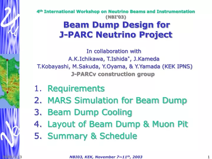
This paper discusses the requirements, simulations, and design considerations for the beam dump cooling system in collaboration with KEK's J-PARC neutrino project. It covers radiation shielding, heat deposition, redundancy, and material choices for efficient cooling. The layout of the beam dump and muon pit is detailed, emphasizing safety and operational longevity.

E N D
4th International Workshop on Neutrino Beams and Instrumentation (NBI’03)Beam Dump Design forJ-PARC Neutrino Project In collaboration with A.K.Ichikawa, T.Ishida*, J.Kameda T.Kobayashi, M.Sakuda, Y.Oyama, & Y.Yamada (KEK IPNS) J-PARCν construction group • Requirements • MARS Simulation for Beam Dump • Beam Dump Cooling • Layout of Beam Dump & Muon Pit • Summary & Schedule NBI03, KEK, November 7~11th, 2003
1. Requirements for BD/MUPIT • Radiation shielding at operation • <11mSv/h at the edge of shield (Outer Concrete – Soil) • Residual dose rate in the muon pit • < 12.5μSv/h for the normal controlled area. • Beam dump cooling • ~¼ of total heat is deposited in the Beam Dump. • Radiation in cooling water • H.E.γ(16N,14O), delayed neutron emission(17N): cooling system should also be shielded and be in underground. • 3H production: We are planning to dispose it (<15Bq/cc) by dilution. Hadron fluence at cooling place should be enough low = Cooling path should be as far as possible from beam center. • Redundancy • Core part is highly radio-active so it is hard to access. • Need to bear 20 years, also for 4MW operation. NBI03, KEK, November 7~11th, 2003
Decay Volume, Beam Dump and MUPIT An updated design will be shown later 110m NBI03, KEK, November 7~11th, 2003
2. MARS Simulation for Beam Dump • Φ- symmetrical geometry with iron + concrete • Δr=10/5cm, Δz=20/5cm, corresponding to OAB 2° • Calculate incoming particle flux, energy deposit, hadron fluence, and dose equivalent of each volume and obtain critical boarder lines for BD design: • Energy Deposit= 0.02Joule/cm3=5,000W/m3 = DV plate coil, boarder between Iron and Concrete. • Hadron Fluence = 1×10⁻⁵ (2×10⁻⁶) /cm2/proton at cooling path for 750kW (4MW) operation • Dose Equivalent =11mSv / hour / (factor), where factor = “Threshold factor” (2)×[Safety(2)] • Former comes if we set neutron energy cutoff threshold (10-3eV→20MeV) in the simulation to save CPU time. • For 4MW operation, latter is taken into account already in the design value NBI03, KEK, November 7~11th, 2003
Φ- symmetrical Geometry • Beam: Δx,y=0.424cm / ΔΘx,y=0.5mrad • HORN Magnetic Field ON/OFF • MUON ProductionON/OFF NBI03, KEK, November 7~11th, 2003
Results:Incoming Particle Flux(1) HORN ON OFF / 100,000 p.o.t. NBI03, KEK, November 7~11th, 2003
Results:Incoming Particle Flux(2) / 100,000 p.o.t. Protons w/o interaction at target (~17%, σx,y= 15cm) NBI03, KEK, November 7~11th, 2003
Results:Energy Deposit and Hadron Fluence Concrete BD Fe 0.02J/cm3 (Fe-Concrete) 16 J/cm3, +4.6℃/spill Fe ~1.5m DV He MUON ~2.5m 2e-6 /cm2/P (Cooling Water Path) ~1.7m ~2.5m NBI03, KEK, November 7~11th, 2003
Results:Energy Deposit with/without Muon Production BD Fe DV He Concrete Possible MUPIT location: Fe 3.5m equivalent NBI03, KEK, November 7~11th, 2003
Results:Dose Equivalent Concrete BD Fe 100 Sv/h (Fe-Concrete) Fe ~1.5m 11mSv/h (Concrete-Soil) DV He Iron 4m + Concrete 1.5m NBI03, KEK, November 7~11th, 2003
3. Beam Dump Cooling • Compared to K2K, JPARCν project employs ×150 intense beam. An efficient cooling is necessary. • Choice of core material • Input: MARS simulation energy deposit, scaled by material density. • Check temperature distribution both by static calculation and by transient heat simulation by NASTRAN code. NBI03, KEK, November 7~11th, 2003
Temperature distribution at Equilibrium Q( r) T(r )-TR 600 100 300 α(Δt=50℃) 500 2000 1.5m 1.5m Ex. Core material: Cu(λ=400W/m・K) 4MW 750kW T(r=0)-T(1.5m)=125℃ α(1.5m)=600W/m2K T(r=0)-T(60cm)=300℃ α(60cm)=4kW/m2K T(r=0)~125+50+30=200℃ NBI03, KEK, November 7~11th, 2003
Comparison of Core Material Candidates In case of Cooling at r=1.5m • Higher density = higher local energy deposit = smaller core size = smaller amount of water • Cu has the highest heat conductivity. = further cooling water path = lower hadron fluence at cooling surface NBI03, KEK, November 7~11th, 2003
Transient heat analysis (NASTRAN) Cooled with Conv. Coef. =600W/m2・K • Consistent to the • analytic calc. • 750kW is OK with • Copper core. • Need measure • for 4MW. NBI03, KEK, November 7~11th, 2003
Cooling Water and Its Treatment(rough estimation) 1.5m 1.5m • What we need: • 2×1.5×π×1.5=14.1m2, × α=700W/m2K • Cool core by 1inchφ×20 pathes • 750kW×1/4×1/20 = 9.4kW/path • Total amount of water in tubes = 13 litter • Water flow rate = 30litter/min = 1.16m/s ⇒ ΔTwater=4.5℃, α=4.9kW/m2K • Inner surface area in total = 2.2m2 ⇒ 2.2×4.9 ~ 14.1×0.7 • Water system: • A circulation path with heat exchanger + a dilution path. • The dilution path= a deposit tank + a dilution tank to dispose water with < 15Bq/cc. • BD: 2.6m3 when diluted to 15Bq/cc equivalent. • Details was presented in “Radiation Safety Issues” NBI03, KEK, November 7~11th, 2003
4. Layout of Beam Dump and Muon Pit Core Cu 230t Cooling path Mu Pit Iron block 660t (DURATEC?) Temp. raise Air: +1℃/1.2h Conc:+1℃/1.8h (Air conditioned) Dose Equivalent ~100(40) mSv/h Residual Dose (30d/1d) 0.2(0.05) uSv/h Cooling pit (Heat Exchange) NBI03, KEK, November 7~11th, 2003
Hadron Fluence 2e-6 /cm2/P (Cooling Water Path) DOSEEq. 11mSv/h (Concrete-Soil) 100 Sv/h (Fe-Concrete) NBI03, KEK, November 7~11th, 2003
5. Summary • A possible BD/MUPIT design is shown. • Materials to MUPIT: Eμ>4.5GeV Copper core(1.5m)+Iron block(1.5m)+Concrete(0.5m) Hadron Fluence / residual dose at MUPIT is low enough. • Hadron fluence at cooling path around core is equal to or less than that of DV plate coil, to dispose it with < ×200 dilution. • Convection coef.=700W/m2・K for 750kW operation is enough realistic. • Detailed BD core design is under progress. • Need measure for 4MW operation. This can be achieved with a cooling path at around r=60cm. • Requirements for muon profile monitor settled after BD (J.Kameda) • Good sensitivity for magnet and proton beam position with 2~5 GeV/c threshold and no big difference in this region. • Above ~ 7 GeV/c, the sensitivity become worse. • With 5GeV/c threshold, muon fluence is ~108/spill/cm2. • Possible design is under discussion with physics group. NBI03, KEK, November 7~11th, 2003
Schedule 2004 2005 2006 2007 2008 FY2003 Conceptual design Technical design 07/31 Civil construction Production Installation Core Import Installation Iron block Installation Water system K2K NBI03, KEK, November 7~11th, 2003