Download
1 / 36
360 likes | 548 Views
Explore carrier drift, resistivity, IC fabrication processes, and more. Learn about speed limits in modern transistors and diffusion mechanisms in semiconductor devices.

E N D
Lecture 7: IC Resistors and Capacitors Prof. Niknejad
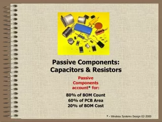
Lecture Outline • Review of Carrier Drift • Velocity Saturation • IC Process Flow • Resistor Layout • Diffusion • Review of Electrostatics • MIM Capacitors • Capacitor Layout University of California, Berkeley
(hole case) x Thermal Equilibrium Rapid, random motion of holes and electrons at “thermal velocity” vth = 107 cm/s with collisions every c = 10-13 s. Apply an electric field Eand charge carriers accelerate … for c seconds University of California, Berkeley
Drift Velocity and Mobility For holes: For electrons: University of California, Berkeley
Mobility vs. Doping in Silicon at 300 oK “default” values: University of California, Berkeley
Speed Limit: Velocity Saturation Thermal Velocity The field strength to cause velocity saturation may seem very large but it’s only a few volts in a modern transistor! University of California, Berkeley
Drift Current Density (Holes) Hole case: drift velocity is in same direction as E The hole drift current density is: University of California, Berkeley
Drift Current Density (Electrons) Electron case: drift velocity is in opposite direction as E The electron drift current density is: Jndr = (-q) n vdn units: Ccm-2 s-1 = Acm-2 University of California, Berkeley
Resistivity Bulk silicon: uniform doping concentration, away from surfaces n-type example: in equilibrium, no = Nd When we apply an electric field, n = Nd Conductivity Resistivity University of California, Berkeley
IC Fabrication: Si Substrate • Pure Si crystal is starting material (wafer) • The Si wafer is extremely pure (~1 part in a billion impurities) • Why so pure? • Si density is about 5 10^22 atoms/cm^3 • Desire intentional doping from 10^14 – 10^18 • Want unintentional dopants to be about 1-2 orders of magnitude less dense ~ 10^12 • Si wafers are polished to about 700 μm thick (mirror finish) • The Si forms the substrate for the IC University of California, Berkeley
IC Fabrication: Oxide • Si has a native oxide: SiO2 • SiO2 (Quartz) is extremely stable and very convenient for fabrication • It’s an insulators so it can be used for house interconnection • It can also be used for selective doping • SiO2 windows are etched using photolithography • These openings allow ion implantation into selected regions • SiO2 can block ion implantation in other areas University of California, Berkeley
IC Fabrication: Ion Implantation oxide • Si substrate (p-type) • Grow oxide (thermally) • Add photoresist • Expose (visible or UV source) • Etch (chemical such as HF) • Ion implantation (inject dopants) • Diffuse (increase temperature and allow dopants to diffuse) P-type Si Substrate N-type diffusion region University of California, Berkeley
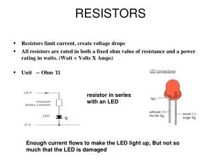
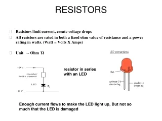
Oxide N-type Diffusion Region “Diffusion” Resistor • Using ion implantation/diffusion, the thickness and dopant concentration of resistor is set by process • Shape of the resistor is set by design (layout) • Metal contacts are connected to ends of the resistor • Resistor is capacitively isolation from substrate • Reverse Bias PN Junction! P-type Si Substrate University of California, Berkeley
Polysilicon Film (N+ or P+ type) Oxide Poly Film Resistor • To lower the capacitive parasitics, we should build the resistor further away from substrate • We can deposit a thin film of “poly” Si (heavily doped) material on top of the oxide • The poly will have a certain resistance (say 10 Ohms/sq) P-type Si Substrate University of California, Berkeley
Ohm’s Law • Current I in terms of Jn • Voltage V in terms of electric field • Result for R University of California, Berkeley
Sheet Resistance (Rs) • IC resistors have a specified thickness – not under the control of the circuit designer • Eliminate t byabsorbing it into a new parameter: the sheet resistance (Rs) “Number of Squares” University of California, Berkeley
Using Sheet Resistance (Rs) • Ion-implanted (or “diffused”) IC resistor University of California, Berkeley
Idealizations • How does current density Jn “turn”? • What is the thickness of the resistor? • What is the effect of the contact regions? University of California, Berkeley
Diffusion • Diffusion occurs when there exists a concentration gradient • In the figure below, imagine that we fill the left chamber with a gas at temperate T • If we suddenly remove the divider, what happens? • The gas will fill the entire volume of the new chamber. How does this occur? University of California, Berkeley
Diffusion (cont) • The net motion of gas molecules to the right chamber was due to the concentration gradient • If each particle moves on average left or right then eventually half will be in the right chamber • If the molecules were charged (or electrons), then there would be a net current flow • The diffusion current flows from high concentration to low concentration: University of California, Berkeley
Diffusion Equations • Assume that the mean free path is λ • Find flux of carriers crossing x=0 plane University of California, Berkeley
Einstein Relation • The thermal velocity is given by kT Mean Free Time University of California, Berkeley
Total Current and Boundary Conditions • When both drift and diffusion are present, the total current is given by the sum: • In resistors, the carrier is approximately uniform and the second term is nearly zero • For currents flowing uniformly through an interface (no charge accumulation), the field is discontinous University of California, Berkeley
+++++++++++++++++++++ − − − − − − − − − − − − − − − Electrostatics Review (1) • Electric field go from positive charge to negative charge (by convention) • Electric field lines diverge on charge • In words, if the electric field changes magnitude, there has to be charge involved! • Result: In a charge free region, the electric field must be constant! University of California, Berkeley
+++++++++++++++++++++ − − − − − − − − − − − − − − − Electrostatics Review (2) • Gauss’ Law equivalently says that if there is a net electric field leaving a region, there has to be positive charge in that region: Electric Fields are Leaving This Box! Recall: University of California, Berkeley
Electrostatics in 1D • Everything simplifies in 1-D • Consider a uniform charge distribution Zero field boundary condition University of California, Berkeley
Electrostatic Potential • The electric field (force) is related to the potential (energy): • Negative sign says that field lines go from high potential points to lower potential points (negative slope) • Note: An electron should “float” to a high potential point: University of California, Berkeley
More Potential • Integrating this basic relation, we have that the potential is the integral of the field: • In 1D, this is a simple integral: • Going the other way, we have Poisson’s equation in 1D: University of California, Berkeley
Boundary Conditions • Potential must be a continuous function. If not, the fields (forces) would be infinite • Electric fields need not be continuous. We have already seen that the electric fields diverge on charges. In fact, across an interface we have: • Field discontiuity implies charge density at surface! University of California, Berkeley
Top Plate Bottom Plate Bottom Plate Thin Oxide IC MIM Capacitor • By forming a thin oxide and metal (or polysilicon) plates, a capacitor is formed • Contacts are made to top and bottom plate • Parasitic capacitance exists between bottom plate and substrate Contacts University of California, Berkeley
Vs + − Review of Capacitors • For an ideal metal, all charge must be at surface • Gauss’ law: Surface integral of electric field over closed surface equals charge inside volume +++++++++++++++++++++ − − − − − − − − − − − − − − − University of California, Berkeley
+++++++++++++++++++++ − − − − − − − − − − − − − − − Capacitor Q-V Relation • Total charge is linearly related to voltage • Charge density is a delta function at surface (for perfect metals) University of California, Berkeley
+++++++++++++++++++++ − − − − − − − − − − − − − − − A Non-Linear Capacitor • We’ll soon meet capacitors that have a non-linear Q-V relationship • If plates are not ideal metal, the charge density can penetrate into surface University of California, Berkeley
What’s the Capacitance? • For a non-linear capacitor, we have • We can’t identify a capacitance • Imagine we apply a small signal on top of a bias voltage: • The incremental charge is therefore: Constant charge University of California, Berkeley
Small Signal Capacitance • Break the equation for total charge into two terms: Incremental Charge Constant Charge University of California, Berkeley
Example of Non-Linear Capacitor • Next lecture we’ll see that for a PN junction, the charge is a function of the reverse bias: • Small signal capacitance: Voltage Across NP Junction Charge At N Side of Junction Constants University of California, Berkeley