Download
1 / 18
180 likes | 192 Views
Learn about the central concepts of electrical circuits including closed circuit current, voltage, resistance, and different circuit types. Discover how to measure current and voltage using ammeters and voltmeters.

E N D
ELECTRICAL CIRCUITS All you need to be an inventor is a good imagination and a pile of junk. -Thomas Edison
Current: continuous flow of electric charges through a material Low Current (high voltage) High Current (low voltage)
Voltage- difference in electric potential between two points (push that causes electrons to move) Low Voltage High Voltage
Resistance: measure of how difficult it is for charges to flow through the objects
Simple Circuits • Series circuit • All in a row • 1 path for electricity • 1 light goes out and the circuit is broken • Parallel circuit • Many paths for electricity • 1 light goes out and the others stay on
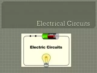
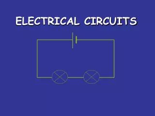
circuit diagram Scientists usually draw electric circuits using symbols; Battery (cell) Light(resister) switch wires
Ohm’s Law • Simple analogy: Water in a hose • Electrons in a copper wire are analogous to water in a hose. • Consider the pressure valve as the applied voltage and the size of the hose as the source of resistance. • The absence of pressure in the hose, or voltage across the wire will result in a system without motion or reaction. • A small diameter hose will limit the rate at which water will flow, just as a small diameter copper wire limits the flow of electrons.
Ohm’s Law Voltage = Current x Resistance Current (amps)= Voltage Resistance Georg Simon Ohm (1787-1854)
Ohm’s Law Current (amps)= Voltage Resistance • the greater the voltage (or pressure) across a resistor, the more the current. • The more the resistance, for the same voltage, the less the current.
Lab Questions: 1. How did adding more voltage affect the current (speed of motor)? 2. How did adding more resistance (lights + motor) affect the current (speed)?
PARALLEL CIRCUIT • Place two bulbs in parallel. What do you notice about the brightness of the bulbs? • Add a third light bulb in the circuit. What do you notice about the brightness of the bulbs? • Remove the middle bulb from the circuit. What happened?
measuring current Electric current is measured in amps(A) using an ammeter connected in series in the circuit. A
measuring current This is how we draw an ammeter in a circuit. A A PARALLEL CIRCUIT SERIES CIRCUIT
measuring voltage The ‘electrical push’ which the cell gives to the current is called the voltage. It is measured in volts (V) on a voltmeter V