Download

1 / 30
• 300 likes • 333 Views
Explore efficient interconnects for clustered microarchitectures to reduce latency and power consumption. Learn about proposed topologies, steering schemes, and experimental results.

E N D
Efficient Interconnects for Clustered Microarchitectures Joan-Manuel Parcerisa Antonio González Universitat Politècnica de Catalunya – Barcelona, Spain{jmanel,antonio}@ac.upc.es Julio Sahuquillo José Duato Universitat Politècnica de València – València, Spain{jsahuqui,jduato}@disca.upv.es
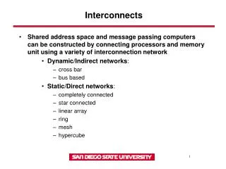
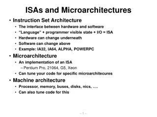
Why Clustered Microarchitectures • Larger issue width, window length, predictor sizes • More complexity more latency and power • Even worse: wire delays do not scale across technologies • Deeper pipelines, fewer logic levels per stage • Tight loops difficult to fit in a single cycle • E.g. issue logic, bypass • Partitioning critical structures attacks both problems • E.g. clustered microarchitectures
Fetch/Decode/Rename Steering Logic Local I-Queue C0 C1 C2 C3 Local Register File FU FU Interconnect-network (ICN) A Typical Clustered uArch • Partitioned processor core • Instructions dynamically steered • Each cluster: RF, IQ, FUs • Faster issue, read, bypass • Inter-cluster communications • Go through slow interconnects • Take 1 cycle or more • Steering must maximize communication locality
Motivation • ICN is a critical part of the architecture • Performance very sensitive to communication latency ! • ICN assumed by previous works • Cross-bar does not scale • Ring simple, but long delays • Idealized Our proposals • Several point-to-point ICN for 4 and 8 clusters • Implementable, simple and efficient • A topology-aware steering
Outline • Clustered architecture • Topology-aware steering • Proposed Interconnects • Experimental results • Summary and conclusions
Our Assumed Clustered uArch • Distributed RF • Results only written to local RF • Values are communicated with copy instructions • Automatically inserted • Each copy creates a new instance • Rename Table tracks locations of multiple instances
(to C1) R1:= R2 + R2 I WB ICN delay Wait for R1 F D I Ex WB (to C2) R3:= R1 + R3 F D I Ex WB Wakeup signals Communication Timing (to C1) copy R1C1->C2
Baseline Steering Scheme(dependence-based) 1. Minimize communication penalty • If all source operands available • Select clusters that minimize # communications • If any source operand not available • Select producer cluster 2. Maximize workload balance • Choose the least loaded of clusters selected by rule 1 One exception: • If workload imbalance > threshold, ignore rule 1
Topology-Aware Steering Scheme • Also minimize distance • Change part of rule 1: If all source operands are available: • Baseline: “Select clusters that minimize # communications” • Topology-aware: “Select clusters that minimize the longest communication distance”
cluster cluster router router Design Issues: Bandwidth • For each additional input bypass path • 1 tag across the IQ • 1 RF write port • 1 entry to FU input MUXes • It increases the wakeup and bypass delays • Bandwidth requirements are rather low • 1 input bypass path per cluster (1 RF write port) • 2 links per connected cluster pair
Design Issues: Latency • Performance very sensitive to communication latency • Simple routing structures and algorithms • Source routing • No intermediate buffering • In-transit messages have priority over newly injected ones
Design Issues: Connectivity • Assumed 1-cycle communication delay between adjacent clusters • Number of “adjacents” dictated by technology and layout • Study topologies with different connectivity degrees
Design Issues: Point-to-point vs Buses • Point-to-point advantages • Access to links is arbitrated locally • Wires are shorter and less loaded • Shared buses are studied for comparison
C0 C1 C2 C3 Interconnects for 4 clusters (I) • Bus2 • 1 Bus per cluster, each connected to 1 write port • Latency = 4 cycles (2 for arbitration + 2 for transmission) • Arbitration overlaps with transmission
Even cycles Odd cycles No conflict! Inject 1-hop message (or forward in-transit) Inject 2-hops message Interconnects for 4 clusters (II) • Synchronous Ring • Injection rules prevent that 2 messages arrive at once: • Even cycles: 1-hop: counter-clockwise/ 2-hops: clockwise • Odd cycles: reverse directions
c1 c0 Input Queues c3 c2 Interconnects for 4 clusters (III) • Partially Asynchronous Ring • Messages may issue in any cycle • 2 messages may arrive at once • Small input queues
Interconnects for 4 clusters (IV) • Ideal Ring • Contention-free • unlimited number of links • unlimited number of RF write ports • For comparison purposes (upper-bound performance)
Interconnects for 8 Clusters (I) • Buses • Analogous to those for 4 clusters • Bus2: same latency (optimistic): 2+2 cycles • Bus4: twice the latency (realistic): 4+4 cycles • Rings • Analogous to those for 4 clusters • Synchronous and Asynchronous • Max. Distance = 4 hops (average 2.29 hops)
Top Left Right Cluster datapath Only for last hop of messages Interconnects for 8 Clusters (II) • Mesh • Max. distance = 4 hops (average = 2 hops) • 2 in-transit messages may compete for the same output link • Constrained connectivity
Only for last hop of messages Interconnects for 8 Clusters (III) • Torus • Max. distance = 3 hops • Same connectivity constraints as the mesh
Interconnects for 8 Clusters (IV) • Ideal Torus • Contention-free • unlimited number of links • unlimited number of RF write ports • For comparison purposes (upper-bound performance)
Top Link Qin Router Structures • Common features to all ICN • No intermediate buffering LeftLink RightLink • Partially asynchronous ICN • Competence for a write port • Add small input queues • Topologies with 3 adjacent nodes • Competence for the same output link • Constrained connectivity Cluster Datapath
Experimental Setup • Simulation • Extended version of sim-outorder (SimpleScalar v3.0) • 14 Mediabench programs • Compiled with –O4 for an Alpha AXP • Architecture • L1 D-cache: 64KB, 2-way, 3-cycle hit • 128 ROB, 64 LSQ • Each cluster: 2-way issue, 16-entry IQ, 56 physical regs.
Performance: 4 Clusters • Poor performance of Bus2 • Asynchronous Ring • Better than Synchronous Ring • Close to Ideal (within 1%)
Synchronous / Asynchronous • Contention delays • Lower for Async. Ring • Message issues as soon asthe link is available • Higher for 1-hop messages • a single path • Sync. Ring: issue 1 cycle every 2
Length of Input Queues • Max. observed occupancy < 9 entries • Handle overflows by flushing the pipeline • Rather than including complex control flow Sample statistics (djpeg)
Performance: 8 Clusters • Poor performance of buses • Connectivity degree has a significant impact • Asynchronous Torus close to Ideal (within1.5%)
Topology-Aware Steering 16.5% IPC improvement with 8 clusters (2.5% with 4 clusters)
Summary • An efficient topology-aware steering scheme • Cluster point-to-point interconnects • For 4 clusters and 8 clusters • Designed to minimize complexity and latency • Compared to • Bus-based models • Idealized models with unlimited bandwidth
Conclusions • The choice of ICN is crucial for performance • Point-to-point better than buses • Asynchronous rings better than synchronous • Asynchronous interconnects perform close to ideal • with minimal complexity • Higher connectivity significantly improves performance • Topology-aware steering essential to reduce latency • Especially with many clusters