Download
1 / 29
330 likes | 682 Views
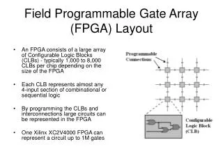
Field Programmable Gate Array. What is FPGA?. XGP Simulator. FPGA. Programmable (= reconfigurable) Digital System Component Basic components Combinational logics Flip Flops Macro components Multiplier ( large combinational logic) Random Access Memory (Large Density)

E N D
FPGA • Programmable (= reconfigurable) Digital System • Component • Basic components • Combinational logics • Flip Flops • Macro components • Multiplier ( large combinational logic) • Random Access Memory (Large Density) • Read Only memory (Large Density) • CPU • Programmable Interconnection • Programmable Input/Output circuit • Programmable Clock Generator
CL A f B C g D What is Combinational Logic? • If output f, g are function of only inputs (A, B, C, D) then the circuit is combinational circuit. • In another word, output signal is determined by only the combination of input signals. • f = func1(A, B, C, D) • g = func2(A, B, C, D) • Combinational logic does NOT include memories such as Flip-Flops. • Combinational logic can be constructed by just primitive gates such as NOT, NAND, NOR, etc. (But no feedback loop) A, B, C, D, f, g are all binary signal.
Combinational Logic realization - gates - • There is no signal loop in the circuit. • In combinational logic, signal loop is prohibited since the loop makes states (Memory). • Function is not configurable.
A 0 0 B 0 C 0 f 0 0 1 1 Decoder Combinational Logic realization - Table - TRUTH TABLE • Function is configurable by storing the TABLE values.
D Q D Q CLK Q D Q Q CLK Q Q Clocked D LATCH • 1 bit memory by NOR cross-loop • When CLK=1, Q = D, /Q=not(D) • When CLK=0, Q holds previous data. When CLK=‘1’ When CLK=‘0’ CIRCUIT SYMBOL:
D D Q Q CLK CLK Q D CLK D Q Master-Slave D Flip-Flop • 2 LATCHES in series • Still work as 1 bit memory • CLK edge Trigger Operation • Most commonly used memory element in the state-of-the-art synchronous Digital Design. • Q only changes CLK edge (once in one cycle). CLK D Q 1 1 0 1 0 CIRCUIT SYMBOL:
CL CL CL CL D D D D D D Q Q Q Q Q Q Digital System is just FF + CLs • FPGA supports such digital circuit with configurability. • FPGA’s basic element
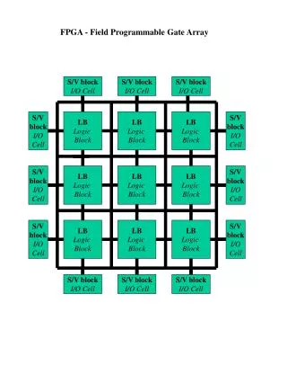
XILINX FPGA • Field Programmable Gate Array
XILINX XC3000 Family I/O • Electronic Static Discharge Protection • CMOS, TTL input • Registered /Non Registered I/O
XILINX XC3000 Family CLB • CLB: Configurable Logic Block • Look-up table for combinational logic • D-Flip-Flops • Look-up Table = RAM
XILINX XC4000 Family CLB • Two Stage Look-up Table
XILINX VIRTEX FAMILY ARCHITECTURE • CLB: Configurable Logic Block • Many 4Kbit RAM BLOCK RAM • DLL (Delay-Locked Loops) to provide controlled-delay clock networks • Multiplier (18b x 18b) Macro also supported (not in figure)
XILINX VIRTEX FAMILY CLB • CLB: Configurable Logic Block • Many 4Kbit RAM BLOCK RAM • DLL (Delay-Locked Loops) to provide controlled-delay clock networks
XILINX VIRTEX FAMILY I/O • Electronic Static Discharge Protection • CMOS, TTL input • Registered /Non Registered I/O
ALTERA CPLD • Complex Programmable Logic Devices • Altera uses less routing resource than Xilinx • Altera’s Logic Array Block (LAB) is more complex than Xilinx’s CLBs. Then fewer LABs in on chip than Xilinx’s CLBs.
ALTERA FLEX8000 ARCHITECURE • Each LAB has eight LEs (Logic Elements) .
ALTERA FLEX8000 Logic Element (LE) • CARRY, CASCADE signals
ALTERA APEX 20K ARCHITECTURE • MANY RAMs • Large Number Input combinational logic such as Multiplier • Phase Locked Loop for Advanced Clock generation
Multiplier ROM I/O circuit Your Circuit RAM CPU RAM ROM How to Design your Digital Systemusing Hard-Macro Blocks • White Blocks might be available (Hardware pre-designed Blocks) SoftWarefor CPU
Hardware Description Languages (HDLs) • HDL is a software programming language used to model the intended operation of a piece of hardware. • Two level of modeling • Abstract behavior modeling • Hardware structure modeling: Input to Circuit Synthesis • Two kinds of Language • VHDL: Very High Speed Integrated Circuit hardware description language • Similar to Pascal Programming language • Verilog HDL: • Similar to C Programming language
library IEEE; use IEEE.std_logic_1164.all; entity HALF_ADDER is port ( A, B : in std_logic; S, C : out std_logic ); end HALF_ADDER; architecture STRUCTURE of HALF_ADDER isbeginS <= A xor B;C <= A and B; end STRUCTURE; module HALF_ADDER (A, B,S, C); input A, B;output S, C; assign S = A ^ B;assign C = A & B;endmodule HALF_ADDER example VHDL Verilog HDL
library IEEE; use IEEE.STD_LOGIC_1164.all; use IEEE.STD_LOGIC_ARITH.all; entity AVG4 is port(CLK : in std_logic; FMINPUT : in std_logic_vector(7 downto 0); AVGOUT : out std_logic_vector(7 downto 0)); end AVG4; architecture RTL of AVG4 is signal FF1, FF2, FF3, FF4 : std_logic_vector(7 downto 0); signal SUM : std_logic_vector(9 downto 0); begin -- SHIFT REGISTER process(CLK) begin if (CLK'event and CLK = '1') then FF1 <= FMINPUT; FF2 <= FF1; FF3 <= FF2; FF4 <= FF3; end if; end process; -- SUM SUM <=signed(FF1(7)&FF1(7)&FF1)+signed(FF2(7)&FF2(7)&FF2) +signed(FF3(7)&FF3(7)&FF3)+signed(FF4(7)&FF4(7)&FF4); -- DIVIDE BY 4 (SHIFT 2 bit), OUTPUT REGISTER process(CLK) begin if (CLK'event and CLK='1') then AVGOUT <= SUM(9 downto 2); end if; end process; end RTL; Moving Average Filter by VHDL