Download
1 / 27
270 likes | 309 Views
Learn about phasor diagrams, peak and RMS values in AC circuits, relationship between voltage and current in resistors, inductors, and capacitors, Kirchoff's loop equation, and practice examples.

E N D
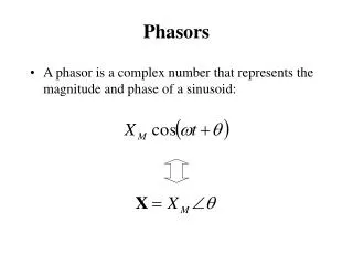
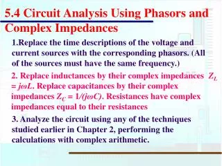
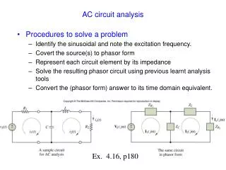
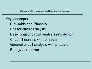
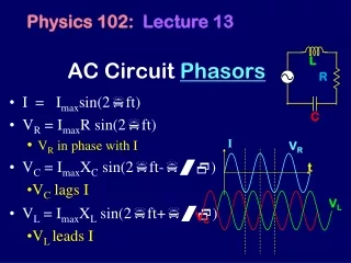
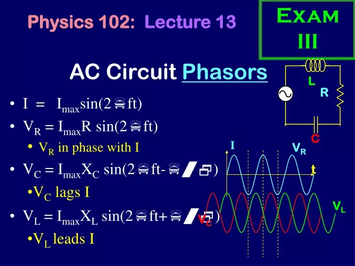
Exam III L R C Physics 102:Lecture 13 AC Circuit Phasors • I = Imaxsin(2pft) • VR = ImaxR sin(2pft) • VR in phase with I I VR • VC = ImaxXC sin(2pft-p/2) • VC lags I t VL • VL = ImaxXL sin(2pft+p/2) • VL leads I VC
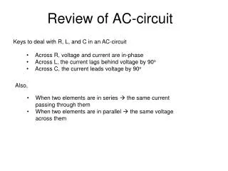
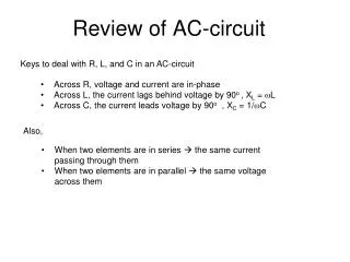
L R C Peak + RMS values in AC Circuits (REVIEW) When asking about RMS or Maximum values relatively simple expresions 5
L R C Time Dependence in AC Circuits Write down Kirchoff’s Loop Equation: VG + VL + VR + VC = 0 at every instant of time • However … • VG,max VL,max+VR,max+VC,max • Maximum reached at different times • for R,L,C 5
q+p/2 a a q q-p/2 a A reminder about sines and cosines y Recall: y coordinates of endpoints are • asin(q + p/2) • asin(q) • asin(q - p/2) x
L R C q+p/2 ImaxR ImaxXL q q-p/2 ImaxXC Graphical representation of voltages I = Imaxsin(2pft) (q = 2pft) VL = ImaxXLsin(2pft + p/2) VR = ImaxR sin(2pft) VC = ImaxXC sin(2pft - p/2)
Phasor Diagrams t = 1 f=1/12 2pft = p/6 • I = Imaxsin(p/6) • VR = VR,maxsin(p/6) VR,max VR,maxsin(p/6) p/6 Length of vector = Vmax across that component Vertical component = instantaneous value of V 10
VR,max Phasor Diagrams t = 2 2pft = p/3 • I = Imaxsin(p/3) • VR = VR,maxsin(p/3) VR,maxsin(p/3) p/3 Length of vector = Vmax across that component Vertical component = instantaneous value of V
VR,max Phasor Diagrams t = 3 2pft = p/2 • I = Imaxsin(p/2) • VR = VR,maxsin(p/2) VR,maxsin(p/2)=V0 p/2 Length of vector = Vmax across that component Vertical component = instantaneous value of V
Phasor Diagrams t = 4 2pft = 4p/6 • I = Imaxsin(4p/6) • VR = VR,maxsin(4p/6) VR,max VR,maxsin(4p/6) 4p/6 Length of vector = Vmax across that component Vertical component = instantaneous value of V
VR,max Phasor Diagrams t = 6 2pft = p • I = Imaxsin(p) • VR = VR,maxsin(p) p VR,maxsin(p)=0 Length of vector = Vmax across that component Vertical component = instantaneous value of V
Phasor Diagrams t = 8 2pft = 8p/6 • I = Imaxsin(8p/6) • VR = VR,maxsin(8p/6) 8p/6 VR,max VR,maxsin(8p/6) Length of vector = Vmax across that component Vertical component = instantaneous value of V
Phasor Diagrams t = 10 2pft = 10p/6 • I = Imaxsin(10p/6) • VR = VR,maxsin(10p/6) 10p/6 VR,maxsin(10p/6) VR,max Length of vector = Vmax across that component Vertical component = instantaneous value of V
VL • Resistor vector: to the right • Length given by VR (or R) VR (2) Inductor vector: upwards • Length given by VL (or XL) (3) Capacitor vector: downwards • Length given by VC (or XC) VC VL VR (5) Rotate entire thing counter-clockwise • Vertical components give instantaneous voltage across R, C, L VC Drawing Phasor Diagrams (4) (coming soon) 15
ImaxXL ImaxR ImaxXL cos(2pft) ImaxR sin(2pft) ImaxXC -ImaxXC cos(2pft) Phasor Diagrams Instantaneous Values: • I = Imaxsin(2pft) • VR = ImaxR sin(2pft) • VC = ImaxXC sin(2pft-p/2) • = -ImaxXC cos(2pft) • VL = ImaxXL sin(2pft+ p/2) • = ImaxXL cos(2pft) Voltage across resistor is always in phase with current! Voltage across capacitor always lags current! Voltage across inductor always leads current! 17
Phasor Diagram Practice Example Label the vectors that corresponds to the resistor, inductor and capacitor. Which element has the largest voltage across it at the instant shown? 1) R 2) C 3) L Is the voltage across the inductor 1)increasing or 2) decreasing? Which element has the largest maximum voltage across it? 1) R 2) C 3) L Inductor Leads Capacitor Lags VR VL R: It has largest vertical component VC Decreasing, spins counter clockwise Inductor, it has longest line. 21
“phase angle” KVL: Impedance Triangle • Instantaneousvoltage across generator (Vgen) must equal sum of voltage across all of the elements at all times: ImaxXL=VL,max Vmax,gen=ImaxZ Vgen (t) = VR (t)+VC (t)+VL (t) Imax(XL-XC) f Vgen,max = Imax Z ImaxR=VR,max ImaxXC=VC,max 25
ImaxR Imax 2pft + f 2pft Phase angle f I = Imaxsin(2pft) Vgen = ImaxR sin(2pft + f) f is positive in this particular case.
VL • Resistor vector: to the right • Length given by VR (or R) VR (2) Capacitor vector: Downwards • Length given by VC (or XC) Vgen (3) Inductor vector: Upwards • Length given by VL (or XL) VC (4) Generator vector: add first 3 vectors • Length given by Vgen (or Z) Vgen Drawing Phasor Diagrams VL VR (5) Rotate entire thing counter-clockwise • Vertical components give instantaneous voltage across R, C, L VC 27
Vgen VR Vgen VR VR VR Vgen Vgen time 4 time 3 time 1 time 2 ACTS 13.1, 13.2, 13.3 When does Vgen = 0 ? time 2 When does Vgen = VR ? time 3 30
f time 4 time 3 time 1 time 2 ACTS 13.1, 13.2, 13.3 When does Vgen = 0 ? time 2 When does Vgen = VR ? time 3 The phase angle is: (1) positive (2) negative (3) zero? negative Look at time 1: Vgen is below VR 31
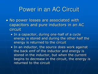
Power P=IV • The voltage generator supplies power. • Resistor dissipates power. • Capacitor and Inductor store and release energy. • P = IV so sometimes power loss is large, sometimes small. • Average power dissipated by resistor: P = ½ Imax VR,max = ½ Imax Vgen,max cos(f) = Irms Vrms cos(f) 34
AC Summary Resistors: VRmax=I R In phase with I Capacitors: VCmax =I XC Xc = 1/(2pf C) Lags I Inductors: VLmax=I XL XL = 2pf L Leads I Generator: Vgen,max=I Z Z= sqrt(R2 +(XL-XC)2) Can lead or lag I tan(f) = (XL-XC)/R Power is only dissipated in resistor: P = ½ImaxVgen,max cos(f) 37
L R C Problem Time! Example An AC circuit with R= 2 W, C = 15 mF, and L = 30 mH is driven by a generator with voltage V(t)=2.5 sin(8pt) Volts. Calculate the maximum current in the circuit, and the phase angle. 41
L R C Problem Time! Example An AC circuit with R= 2 W, C = 15 mF, and L = 30 mH is driven by a generator with voltage V(t)=2.5 sin(8pt) Volts. Calculate the maximum current in the circuit, and the phase angle. Imax = Vgen,max /Z Imax = 2.5/2.76 = .91 Amps 41
Preflight 13.1 The statement that the voltage across the generator equals the sum of the voltages across the resistor, capacitor and inductor is true for: (1) instantaneous voltages only (2) rms voltages only (3) both rms and instantaneous 33% 32% 35% ImaxXL=VL,max Vgen,max Imax(XL-XC) Rotates Counter Clockwise f ImaxR Vgen=VL+VR+VC at all times. Vrms does not! ImaxXC = VC,max 43
Imax XL Vgen,max f Imax R Imax XC ACT: Voltage Phasor Diagram At this instant, the voltage across the generator is maximum. What is the voltage across the resistor at this instant? 1) VR = ImaxR 2) VR = ImaxR sin(f) 3) VR = ImaxR cos(f) 46