Download
1 / 24
250 likes | 672 Views
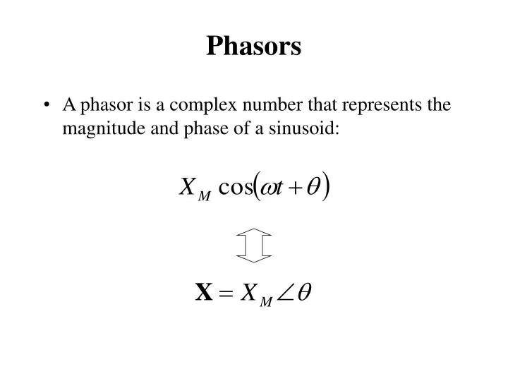
Phasors. A phasor is a complex number that represents the magnitude and phase of a sinusoid:. Complex Exponentials. A complex exponential is the mathematical tool needed to obtain phasor of a sinusoidal function. A complex exponential is e j w t = cos w t + j sin w t

E N D
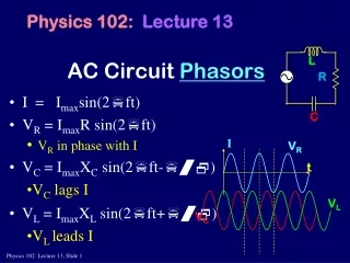
Phasors • A phasor is a complex number that represents the magnitude and phase of a sinusoid:
Complex Exponentials • A complex exponential is the mathematical tool needed to obtain phasor of a sinusoidal function. • A complex exponential is ejwt= cos wt + j sin wt • A complex number A = z q can be represented A = z q = z ejq = z cos q + j z sin q • We represent a real-valued sinusoid as the real part of a complex exponential. • Complex exponentials provide the link between time functions and phasors. • Complex exponentials make solving for AC steady state an algebraic problem
Complex Exponentials (cont’d) What do you get when you multiple A withejwt for the real part? Aejwt = z ejqejwt = z ej(wt+q) z ej(wt+q) = z cos (wt+q) + j z sin (wt+q) Re[Aejwt] = z cos (wt+q)
Sinusoids, Complex Exponentials, and Phasors • Sinusoid: z cos (wt+q)= Re[Aejwt] • Complex exponential: Aejwt = z ej(wt+q), A= z ejq, • Phasor for the above sinusoid: V = z q
Phasor Relationships for Circuit Elements • Phasors allow us to express current-voltage relationships for inductors and capacitors much like we express the current-voltage relationship for a resistor.
+ i(t) v(t) C - I-V Relationship for a Capacitor Suppose that v(t) is a sinusoid: v(t) = VM ej(wt+q) Find i(t).
Phasor Relationship • Represent v(t) and i(t) as phasors: V = VMq I = jwCV • The derivative in the relationship between v(t) and i(t) becomes a multiplication by jw in the relationship between V and I.
I-V Relationship for an Inductor V = jwLI + i(t) v(t) L -
Kirchhoff’s Laws • KCL and KVL hold as well in phasor domain.
Impedance • AC steady-state analysis using phasors allows us to express the relationship between current and voltage using a formula that looks likes Ohm’s law: V = IZ • Z is called impedance.
Impedance (cont’d) • Impedance depends on the frequency w. • Impedance is (often) a complex number. • Impedance is not a phasor (why?). • Impedance allows us to use the same solution techniques for AC steady state as we use for DC steady state. • Impedance in series/parallel can be combined as resistors
Impedance Example:Single Loop Circuit w = 377 Find VC 20kW + + VC 10V 0 1mF - -
Impedance Example (cont’d) • How do we find VC? • First compute impedances for resistor and capacitor: ZR = 20kW= 20kW 0 ZC = 1/j (377 1mF) = 2.65kW -90
Impedance Example (cont’d) 20kW 0 + + VC 2.65kW -90 10V 0 - -
W Ð ° æ ö 2 . 65 k - 90 = Ð ° ç ÷ V 10V 0 C W Ð ° + W Ð ° 2 . 65 k - 90 20 k 0 è ø Impedance Example (cont’d) Now use the voltage divider to find VC:
Analysis Techniques • All the analysis techniques we have learned for the linear circuits are applicable to compute phasors • KCL&KVL • node analysis/loop analysis • superposition • Thevenin equivalents/Notron equivalents • source exchange • The only difference is that now complex numbers are used. • Phasors can then converted to corresponding sinusoidal functions to get the time-varying function.
Impedance • V = IZ, Z is impedance, measured in ohms () • Resistor: • The impedance is R • Inductor: • The impedance is jwL • Capacitor: • The impedance is 1/jwC
Analysis Techniques • All the analysis techniques we have learned for the linear circuits are applicable to compute phasors • KCL&KVL • node analysis/loop analysis • superposition • Thevenin equivalents/Notron equivalents • source exchange • The only difference is that now complex numbers are used. • Phasors can then converted to corresponding sinusoidal functions to get the time-varying function.
Admittance • I = YV, Y is called admittance, the reciprocal of impedance, measured in siemens (S) • Resistor: • The admittance is 1/R • Inductor: • The admittance is 1/jwL • Capacitor: • The admittance is jwC
Phasor Diagrams • A phasor diagram is just a graph of several phasors on the complex plane (using real and imaginary axes). • A phasor diagram helps to visualize the relationships between currents and voltages.
+ + VC 1mF – V + 1kW VR – – An Example 2mA 40 • I = 2mA 40 • VR = 2V 40 • VC = 5.31V -50 • V = 5.67V -29.37
Phasor Diagram Imaginary Axis Real Axis V VC VR
Homework #9 • How to determine initial conditions for a transient circuit. When a sudden change occurs, only two types quantities will definitely remain the same before and after the change. • IL(t), inductor current • Vc(t), capacitor voltage • Find these two types of the values before the change and use them as initial conditions of the circuit after change