Download
1 / 46
460 likes | 475 Views
Learn about NEC coordination requirements for Automatic Transfer Switches in mission-critical facilities. Selective coordination, device settings, legal standards & more explained by expert John Stark.

E N D
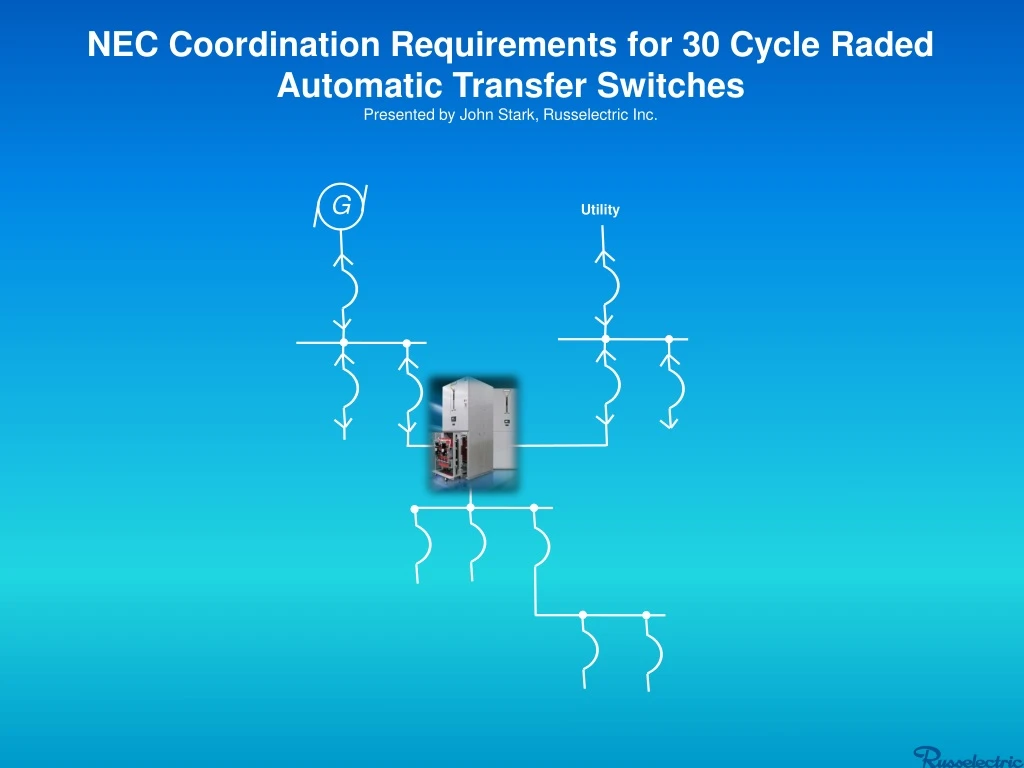
G Utility ATS NEC Coordination Requirements for 30 Cycle Raded Automatic Transfer Switches Presented by John Stark, Russelectric Inc.
History Starting in 1993, changes to the National Electrical Code (NEC) required the selective coordination of overcurrent protective devices at hospitals and other mission-critical facilities. Article 701.7 (C) of the NEC was added to include Automatic transfer switches as part of the legally required standby system.
Selective Coordination Selective coordination was first required by the NEC in 1993 for elevator circuits. Amendments to the Code in 2005 and 2008 strengthened the requirements and expanded them to include emergency and legally required standby systems, as well as critical operations power systems (COPS). Selective Coordination is a complicated process of coordinating the ratings and settings of overcurrent protective devices, such as circuit breakers, fuses, and ground fault protection relays, to limit overcurrent interruption (and the resultant power outages) to the affected circuit or equipment (the smallest possible section of a circuit). In other words, ideally, the only overcurrent protective device that should open is the device immediately “upstream” from the circuit/equipment experiencing an overcurrent condition.
What is Selective Coordination? Overview cont. • Definition(Article 100 – NEC) • Localization of an overcurrent condition to restrict outages to the circuit or equipment affected, accomplished by the choice of overcurrent protective devices and their ratings or settings. Beyond the Code definition, NEC goes on to say: • “For the full range of possible overcurrents, the system is designed to isolate an overloaded or faulted portion of the circuit from the remainder of the electrical system, thereby eliminating unnecessary power outages in the unaffected portions.” • So, ideally, the place in the circuit causing the overcurrent is isolated by the selective operation of the overcurrent protective device which is closest –upstream- to the source of the overcurrent condition.
NEC 2017 –Verbiage on Selective Coordination • NEC(2017) 700.32 Coordination: requires “Emergency system(s) overcurrent devices shall be selectively coordinated with all supply side overcurrent protective devices.” • NEC(2017) 701.27 Coordination: requires “Legally required standby system(s) overcurrent devices shall be selectively coordinated with all supply side overcurrent protective devices.” • NEC(2017) 517.26 Application of other articles: requires “The essential electrical system shall meet the requirements of Article 700.” • The overcurrent protective devices may include the following: • Molded Case Circuit Breakers • Fused devices • Insulated Case Circuit Breakers • Air Power Circuit breakers
Summary The purpose of a legally required standby system is to provide power when the normal supply of electricity is interrupted. This doesn't just mean emergency power for egress, etc., it means power for continuing critical operations. Those operations may be all of the operations at a facility or only specific ones, depending on what the AHJ (Agency Having Jurisdiction) specifies. The motivation for standby power is typically to protect those inside the facility (a hospital being a prime example). It may be something else, such as to keep critical operations (e.g., a sewage plant) running. In some cases, the city that grants the business license mandates that the facility have standby power to prevent the loss of jobs that would occur in the event the facility lost its main power source and suffered huge financial losses as a result . The actual motivation isn't the key; the fact that a government entity mandates the system is.
G APCB's (Air Power Circuit Breaker) are typically 30 cycle withstand devices. ICCB's (Insulated Case Circuit Breaker) ATS MCCB's (Molded Case Circuit Breaker) typically instantaneous or Current Limiting Devices. Example Circuit Utility 4000A APCB 1600A APCB 1600A APCB 800A ICCB 400A MCCB Example: An overcurrent event (overload, short circuit, or ground fault) here ostensibly should trip the nearest overcurrent device
Legally Required Standby Systems What if there’s a fault and overcurrent devices closest to the fault do not trip clear or do not trip clear at its required coordinated setting?
In the absence of other means to satisfy selective coordination, the ATS must withstand a fault or even close on potential fault to be properly coordinated. G Utility 4000A APCB 1600A APCB 1600A APCB Fault on load side of ATS could see up to 30 cycles of fault current -depending on the Air Power Circuit Breaker settings that is feeding it- and could travel through the ATS and the ATS contacts. ATS ATS 800A ICCB If the 400A MCCB does not trip/clear here… Selective Coordination Or here 701.5 Transfer Equipment. 701.5 Transfer Equipment. (A) General. Transfer equipment, including automatic transfer switches, shall be automatic and identified for standby use and approved by the authority having jurisdiction. Transfer equipment shall be designed and installed to prevent the inadvertent interconnection of normal and alternate sources of sup-ply in any operation of the transfer equipment.
G Utility 4000A APCB 1600A APCB 1600A APCB ATS 800A ICCB Selective Coordination Pushback Example: After new code requirements for selective coordination in legally required standby systems were implemented and after transfer switches were included in the conversation, a dilemma arose in that these requirements preceded any available contactor based transfer switches, which could meet the code. As a result, some areas of the country accepted signing off on electrical systems where it could be determined by licensed engineers, that all feeder breaker trip units were coordinated and set so as to trip in proper sequence or so as to not expose equipment to overloads they weren’t designed to handle.
Selective Coordination - Good No overlapping fault current of individual devices. This is coordinated properly. In a perfect world this is great.
Selective Coordination - BAD ATS Feeder Breaker 8 cycles to clear In this case, since it takes 8 cycles for the upstream breaker to clear the fault, a 3 cycle rated transfer switch is inadequate.
Revised – October 2017 WA M I VT ME NH OR NY WI MA ID CT MT ND SD RI Map of NEC Adoption by State M I NYC: 2008 MN IA PA NJ NB MD OH IN DE NV IL UT WY WV VA DC 2011 CO KS MO KY NC TN AZ NM SC AR OK GA MS CA AL AK TX FL . 2017 NEC – 14 States = States that are also subject to local adoption HI 2008 NEC – 3 States NEC – 6 States No Statewide Adoption – 5 2011 2014 NEC – 23States LA Note: Earlier editions of the NEC may be enforced in states with no statewide adoption or that are subject to local adoption.
Most Complete Range of Engineered 30 Cycle Rated, UL-1008 Listed and Labeled Transfer Switches to Simplify Selective Coordination
Why 30 Cycle? Where does that number come from? Is it mandated by the code or UL 1008? No When designing transfer switching equipment with the intent of contributing to the overall integrity of an electrical system to achieve selective coordination, design and ratings choices are made by the individual transfer switch manufacturers. As far as Russelectric is concerned, we have elected to design to the worst possible exposure in terms of time duration of a fault. Because overcurrent devices could be applied anywhere from instantaneous trip to short time trip all the way up to 30 cycles, we have decided to design to the worst possible exposure. I.E. 30 cycles. John Stark – Russelectric Inc.
UL 1008 Withstand TestUL Standard for Safety for Transfer Switch Equipment, UL 1008Eighth Edition, Dated December 22, 2014 Before we talk about achieving a 30 cycle close and withstand rating, lets first review the UL-1008 Standard for Safety for Transfer Switch Equipment. This is the standard that all UL-1008 labeled transfer switches have passed.
UL 1008 (short circuit) Withstand TestUL Standard for Safety for Transfer Switch Equipment, UL 1008Eighth Edition, Dated December 22, 2014 Criteria for Test Results 9.13.3.4 For all transfer switches, (a) – (g) a) The (grounding) fuse mentioned in 9.13.3.29 shall not open; b) There shall be no breakage of the switch base to the extent that the integrity of the mounting of live parts is impaired; c) The door shall be prevented by its latch, without bolt or lock installed therein, from opening; d) No conductor shall have pulled out of a terminal connector and there is no damage to the conductor insulation or the conductor; e) For a plug in or draw out unit, the point of contact shall be the same both mechanically and electrically as before the test; f) The interlocking mechanism shall continue to operate in the intended manner. In addition, all wiring connections shall be examined to determine that there has been no adverse effect – for example, connections shall not become loose, parts shall not rotate, and the like; and g) The transfer switch shall comply with the requirements in the Dielectric voltage-withstand test, 9.9, except that the test potential shall be twice the rated voltage of the switch, but not less than 900 V. 9.13.3.5 Other than as noted in 9.13.3.6, the tests specified in this clause shall be performed on both the normal source and alternate source circuits.
UL 1008 Overload (6x Current) Test Table 19 Overload Test Table 19 Transfer switch equipment shall perform in an acceptable manner, as intended by the manufacturer, when subjected to an overload test consisting of the number of operations specified in Table 19, controlling a test current as described in Table 28.2. Table 18 Method of determining test current for overload tests on transfer switches An operational cycle is defined as making and breaking the required test current on both the normal and alternate contacts. During the test, the alternate source shall be displaced 120 electrical degrees from the normal source for a 3 phase supply or 180 electrical degrees for a single phase supply. The minimum on time in each contact position is to be 1/6 second (ten electrical and operational cycles based on a 60Hz source), unless automatic tripping of the over-current device occurs.
UL 1008 Endurance Test AKA Switching Operations Test Revision 12/22/14 Table 22 (not shown) The test cycle is to be 1 second “on” and 59 seconds “off”. A controller may be operated at a rate of more than 1 cycle per minute if synthetic loads are used or if a sufficient number of banks of lamps controlled by a each bank will cool for at least 59 seconds between successive applications of current. Table 23 Endurance test cycles for emergency system switches including legally required stand-by systems. Switch rating
UL 1008 Temperature Test 29.1 Transfer switches when tested under the conditions described in 29.2 – 29.12 shall not attain a temperature at any point high enough to constitute a risk of fire or to damage any materials employed in the device, and shall not show temperature rises at specific points greater than those indicated in Table 29.1 29.2 For the temperature test the transfer switch is to be operated under intended use conditions and is to carry its test current continuously at the test potential specified in Table 24.1. 29.3 The test current shall be 100 percent of the rated current. All Russelectric transfer switches have passed true UL-1008. Tests are performed with Underwriters Labratories witnessing, without exception.
30 Cycle Close and Withstand Test Russelectric’s complete line of RTS-30 (30 cycle transfer switches) in automatic, manual, bypass/isolation, open transition, closed transition, have passed close and withstand tests, conducted with UL, for the full range of their low voltage line.
Russelectric30 Cycle Automatic Transfer Switchesand Bypass Isolation Switches
Russelectric 3 Cycle Design Blow-Off Design Single Arcing Contact Multiple Contact Fingers depending on amperage Main Contact Pad material: AgWC50 – Silver Tungsten Carbide Tungsten to reduce erosion Arcing Pad Material: AgW73 – Silver Tungsten Stationary Contact Pad material: AgWC50 – Silver Tungsten Carbide Contacts Rotate on Copper Hinge Block and Pin Assembly Metal Contact Holder Contact Comparison: 3 Cycle vs. 30 Cycle
Movable and Arcing Contact Springs Movable Arcing Contact Current Path Blow Open Force Stationary Contact Movable Main Contact Contact Design: Blow-off vs. Blow-on Blow-Off Contact Design (used on our 3 cycle switches): - Used for Interrupting High Fault Currents - Magnetic forces push contacts open - Used for 3 cycle devices - Contact springs - only force to withstand fault
30 Cycle Design Blow-On Design Arcing Contact Designed into each main contact – Copper Multiple Contact Fingers depending on amperage Main Contact Pad material: AgWC40 – Higher Silver Content to prevent overheating by dissipating heat faster Stationary Contact Pad material: AgC4 – 96% Silver, graphite to prevent welding during withstand Flexible Braided connectors – prevents overheating and hot spots Brush Movement in Main Contacts – Cleans contact pad every operation Molded Contact Holder - Contains arc - BMC thermoset material - Withstands heat - Great arc and track resistance
Contact Design: Blow-on (used on our 30 cycle switches) • - Used for withstanding High Fault Currents • - Magnetic forces from fault increase pressure on contacts • Offset hinge point allows for rotation toward contacts • for blow on effect Contact Springs Hinge Point Force Main Contact Current Path Stationary Contact
BACKPLATE: -increased thickness to 1.25” -added strength and stability Back Plate Assembly • SIDE BARRIER: • 5/8” thk glass polyester • Greater arc & track resistance • Excellent flame resistance • Movable contact support
Crossarm Actuator Mechanism Made from 1.125 Solid Square Steel Stock Overcenter Spring Mechanism to Latch Contacts Closed and Open Utilizes same mechanics as the 3 cycle switch – Heavier spring Extra helper spring for the most effective contact closing
Crossarm Actuator Mechanism – Close-up • Strong MIG Welds
Switchbases • Open Transition Switches with EMO • DC Motor Operators for increased torque
Removal of Isolation Handle • Single Handle is for Bypass Operation • 800A Rollout Switch Cradle rolls out on Ground – not on rails
Gearbox Rack-in Mechanism • Access Rack-in Shaft through door - only in Bypass Mode • Position Indicator Window - Connected - Connected – Bypassed - Test - Isolated • Gearbox needed for Increased Spring Pressure
Finger Clusters • Added Spring Pressure for Clamping • Increased Contact Surface Area • Withstood 100KA for 3 Cycles and 85KA for 30 Cycles - without a trace 2500A Cluster 800A Cluster
Secondary Disconnect • Located on left Side of Cubicle for accessibility • Allows for Test Position • Incorporated into Side Guide- Rail
Guide Plates • Used for Left to Right Alignment • Prevents Rollout Switch from jumping or shifting during fault
Shutter Design (Optional) Shutter Closed (switch in test position or isolated) Shutter Open (switch racked-in)
UL 1008 7th Edition Values Russelectric withstand ratings are good for any manufacturer’s circuit breakers.
Frontrunner Full line of UL – 1008 -Listed and Labeled- 30 cycle Transfer Switches and Bypass/Isolation Switches from 100a through 4000a
Selective Coordination and 30 Cycle Rated Transfer Switches Thank you!