Download
1 / 16
160 likes | 282 Views
Structural Optimization of Composite Structures with Limited Number of Element Properties J. Enrique Herencia University of Bristol, Bristol BS8 1TR, UK Raphael T. Haftka University of Florida, Gainesville, FL 32611, US Vladimir Balabanov Independent Contractor, Mill Creek, WA 98012, US.

E N D
Structural Optimization of Composite Structures with Limited Number of Element PropertiesJ. Enrique HerenciaUniversity of Bristol, Bristol BS8 1TR, UKRaphael T. HaftkaUniversity of Florida, Gainesville, FL 32611, USVladimir BalabanovIndependent Contractor, Mill Creek, WA 98012, US
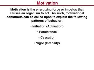
Motivation • Structural optimization, if carried to extreme, may assign different properties to every point in the structure. • From manufacturing and testing viewpoint this is undesirable. • In our previous study of a metallic 10-bar truss, we observed that limiting the number of cross sections had only a small weight penalty. • Present paper looks at the weight penalties for a composite 10-bar truss with a limited number of cross sections and families of laminates
outline • 10-bar truss problem. • Composite laminate families. • Two-level optimization algorithm. • Results • Weight penalties. • Load redistribution and number of active constraints. • Concluding remarks.
Ten-bar truss • L=360”, P1=P2=150kips, P3=300 Kips, acting independently. Each bar square tube made of graphite epoxy.
Composite laminate families • Industry practice is to develop families of laminates with similar percentages of plies • Family of stacking sequences for the 60/30/10 layup (36 laminates) 0.0884[45,-45,0,0,90,0,0,0,45,0,0,0,90,0,0,-45,45] 0.0988[45,-45,0,0,0,90,0,45,0,0,0,45,0,90,0,0,0,-45,45] . . . . 0.2912[45,-45,0,0,90,0,0,0,45,-45,0,0,0,90,0,0,45,-45,0,0,0,90,0,0,45,-45,0,0,0,0,-45,45,0,0,90,0,0,0,-45,45,0,0,90,0,0,0,-45,45,0,0,0,90,0,0,-45,45] 10/80/10 layup, 20/60/20 layup, 50/40/10 layup considered but not selected by optimization algorithm 0/±45/90 degree
Design variables for given number of different cross sections • Vector x of n master cross sectional areas • Vector iof member assignments • Example: n=3, • Members 1 and 8 have a cross sectional area of 9.2.
Problems design variables • Mark on a figure of the truss the cross sectional areas corresponding to • What is the total number of possible different assignment vectors for this case of n=3?
Upper-level optimization problem . Strain (3600με), local and Euler buckling constraints
Square tube design (Lower level optimization) • Choose thickness and adjust width to preserve axial stiffness of ideal laminate while maximizing constraint margin • Drives local and global buckling to occur simultaneously
Optimization algorithm • Convert to unconstrained problem by penalizing weight by , most critical load ratio • Get approximate optimum by genetic algorithm. Freeze locations of master areas within truss and refine by gradient based optimization.
Results: Weight penalty • Only 5.6% penalty for limiting to 4 sections
Load redistribution, Case 1 Black (+) = tension Orange (-) = compression Critical constraints circled.
Load redistributin, case 2 Black (+) = tension Orange (-) = compression Critical constraints circled
Load redistribution Case 3 Black (+) = tension Orange (-) = compression Critical constraints circled
All active constraints 10 buckling critical (7 members, 20 failure modes), 3 strength critical members.
Concluding remarks • Designing with limited number of cross sections proved to be tough computationally. • Penalty for restricting number of sections was not substantial. • Truss structure was mostly designed by buckling constraints. • Large number of critical constraints at optimum indicates that even small weight gain will come at the cost of poorer robustness. • Problem should be addressed with reliability based design.