Download
1 / 37
370 likes | 551 Views
Introduction to 2D Graphics. Using OpenGL. Why Learn About OpenGL?. A well-known industry standard for real-time 2D and 3D computer graphics Available on most platforms Desktop operating systems, mobile devices (OpenGL ES), browsers ( WebGL )

E N D
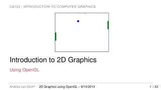
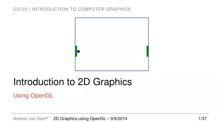
Introduction to 2D Graphics Using OpenGL 2D Graphics using OpenGL – 9/9/2014
Why Learn About OpenGL? • A well-known industry standard for real-time 2D and 3D computer graphics • Available on most platforms • Desktop operating systems, mobile devices (OpenGL ES), browsers (WebGL) • Older (OpenGL 1.0) API provides features for rapid prototyping; newer API (OpenGL 2.0 and newer) provides more flexibility and control • Many old features available in new API as “deprecated” functionality • This year for the first time we will use the new API exclusively 2D Graphics using OpenGL – 9/9/2014
Why Learn 2D first? • A good stepping stone towards 3D – many issues much easier to understand in 2D • no need to simulate lights, cameras, the physics of light interacting with objects, etc. • intro to modeling vs. rendering and other notions • get used to rapid prototyping in OpenGL, both of designs and concepts • 2D is still really important and the most common use of computer graphics, e.g. in UI/UX, documents, browsers 2D Graphics using OpenGL – 9/9/2014
Graphics Platforms (1/4) • Applications that only write pixels are rare • Application Model (AM) is the data being represented by a rendered image • manipulated by user interaction with the application • Graphics Platform is intermediary between App and platform • rendering and interaction handling 2D Graphics using OpenGL – 9/9/2014
Graphics Platforms (2/4) • Graphics Platform runs in conjunction with window manager • Determines what section of the screen is allocated to the application • Handles “chrome” (title bar, resize handles); client area is controlled by application 2D Graphics using OpenGL – 9/9/2014
Graphics Platforms (3/4) • Typically, AM uses client area for: • user interface to collect input to the AM • display some representation of AM in the viewport • This is usually called the scene, in the context of both 2D and 3D applications • Scene is rendered by the scene generator, which is typically separate from the UI generator, which renders rest of UI 2D Graphics using OpenGL – 9/9/2014
Graphics Platforms (4/4) • Early raster graphics packages/libraries/platforms • RamTek library 1981, Apple QuickDraw 1984 • Microsoft's Graphics Display Interface (GDI 1990, now GDI+), Java.awt.Graphics2D • Earliest packages usually had these characteristics: • geometric primitives/shapes, appearance attributes specified in attribute bundles (a.k.a. ”graphical contexts”/”brushes”), • applied modally rather than in a parameter list for each primitive (too many parameters for that) • integer coordinates map directly to screen pixels on output device • immediate mode (no record kept of display commands) • no built-in functions for applying transforms to primitives • no built-in support for component hierarchy (no composite shapes) • Early packages were little more than assembly languages for display device 2D Graphics using OpenGL – 9/9/2014
Problems with Early Graphics Platforms (1/3) Geometric Scalability • Integer coordinates mapped to display pixels affects apparent size of image: large on low-res display & small on high-res display • Application needs flexible internal coordinate representation • floating point is essential • float to fixed conversion required; actually a general mapping 2D Graphics using OpenGL – 9/9/2014
Problems with Early Graphics Platforms (2/3) Display updates • To perform operations on objects in scene, application must keep list of all primitives and their attributes (along with application-specific data) • Some updates are transitory “feedback animations,” only a display change • Consider an interior-design layout application • when user picks up an object and drags to new location, object follows cursor movement • interim movements do not relate to data changes in application model, purely visual changes • application model only updated when user drops object (releases mouse button) • in immediate mode, application must re-specify entire scene each time cursor moves • Alternatively, use a retained mode platform, which will store an internal representation of all objects in scene • called a display model to distinguish it from application model 2D Graphics using OpenGL – 9/9/2014
Problems with Early Graphics Platforms (3/3) Interaction • Consider a simple clock example: • User clicks minute hand, location must be mapped to relevant application object; called pick correlation • Developer responsible for pick correlation (usually some kind of "point-in-bounding box rectangle" test based on pick coordinates) • find top-most object at clicked location • may need to find entire composite object hierarchy from lowest-level primitive to highest level composite • e.g., triangle -> hand -> clock • Solution: retained mode can do pick correlation, as it has a representation of scene 2D Graphics using OpenGL – 9/9/2014
Modern Graphics Platforms (1/2) • Device-independent floating point coordinate system • packages convert “application-space" to "device-space" coordinates • Specification of hierarchy • support building scenes as hierarchy of objects, using transforms (scale, rotate, translate) to place children into parents' coordinate systems • support manipulating composites as coherent objects • Smart Objects (Widgets, etc.) • graphic objects have innate behaviors and interaction responses • e.g., button that automatically highlights itself when cursor is over it 2D Graphics using OpenGL – 9/9/2014
Modern Graphics Platforms (2/2) 2D Graphics using OpenGL – 9/9/2014
Immediate Mode Vs Retained Mode Immediate Mode (OpenGL, DirectX) • Application model: stores both geometric information and non-geometric information in Application Database. • Platform keeps no record of primitives that compose scene 2D Graphics using OpenGL – 9/9/2014
Immediate Mode Vs Retained Mode Retained Mode (WPF, SVG, most game engines) • Application model in app and Display model in platform • Display model contains information that defines geometry to be viewed • Display model is a geometric subset of Application model (typically a scene graph) • Simple drawing application does not need Application model (e.g., clock example) • No right answer on which to use – context-dependent tradeoffs (see Chapter 16) 2D Graphics using OpenGL – 9/9/2014
OpenGL (1/3) • Immediate-mode graphics API • No display model, application must directOpenGL to draw primitives • Implemented in C, also works in C++ • Bindings available for many other programming languages • Cross-platform • Also available on mobile (OpenGL ES*) and in the browser (WebGL) • Different platforms provide ‘glue’ code for initializing OpenGL within the desktop manager (e.g. GLX, WGL) • Labs and projects use Qt library to abstract this away * - ES: “Embedded Systems” 2D Graphics using OpenGL – 9/9/2014
OpenGL (2/3) • Created by Silicon Graphics Inc. (SGI, http://sgi.com) in 1992, now managed by the non-profit Khronos Group (http://khronos.org) • Originally aimed to allow any OpenGL program to run on a variety of graphics hardware devices • Invented when “fixed-function” hardware was the norm • Techniques were implemented in the hardware; OpenGL calls sent commands to the hardware to activate / configure different features • Now supports programmable hardware • Modern graphics cards are miniature, highly parallel computers themselves, with many-core GPUs, on-board RAM, etc. • GPUs are a large collection of highly parallel high speed arithmetic units; several thousand cores! • GPUs run simple programs (called “shaders”): take in vertices and other data and output a color value for an individual pixel. • GLSL, (O)GL Shader Language, is C-like language, control arithmetic pipelines • Implement new features in shaders instead of waiting for hardware vendors to support them in h/w • Your final project (typically a team project) will involve writing your choice of shaders 2D Graphics using OpenGL – 9/9/2014
OpenGL (3/3) • Fixed-function API provides features that make it easier to prototype • e.g., the OGL library implements much of the linear algebra needed to move objects on the screen • GL utility library (“GLU”) provides additional high-level utilities • Programmable API implements most of the fixed-function API for backwards compatibility, but uses shaders for implementation • Only true for desktop; must use shaders exclusively to program with OpenGL ES 2.0+ or WebGL • We will use GLM (OpenGL Mathematics) to do our linear algebra instead of using the Fixed-function API 2D Graphics using OpenGL – 9/9/2014
Shaders • In future labs and your final project you will write your own shaders, but for now we will provide shaders for you. • Various types of input to shaders • Attributes are provided per-vertex • Uniforms are provided per-object; have the same value for a group of vertices • OpenGL has many built in types including vectors and matrices • To provide this input you must provide an identifier (“location”) of the Attribute or Uniform • glGetAttribLocation for attributes • glGetUniformLocation for uniforms • The first lab will go into more detail about how to use these functions 2D Graphics using OpenGL – 9/9/2014
Representing Shapes • Objects in OpenGL are composed of triangles and quads. We can use these to build arbitrary polygons, and approximate smooth shapes. An approximate circle made of triangle primitives A complex polygon made of triangle primitives A complex polygon made of quad primitives 2D Graphics using OpenGL – 9/9/2014
Coordinate Systems (1/3) • Cartesian coordinates in math, engineering • typically modeled as floating point • typically X increasing right, Y increasing up • Display (physical) coordinates • integer only • typically X increasing right, Y increasing down • 1 unit = 1 pixel • But we want to be insulated from physical display coordinates • OpenGL is the intermediary 2D Graphics using OpenGL – 9/9/2014
Coordinate Systems (2/3) • OpenGL Coordinates • Choose a convention • For us: X increases right, Y increases up • Units are based on the size of the window or screen • Visible area stretches to fill window • Units are percentage of window size, don’t correspond to physical units or pixels • Define coordinate system using the projection matrix. Supply it to shader as a uniform variable (the term projection matrix will become clear) • Note: 3d glm functions still work in the special case of 2D – just use our defaults glm::mat4 projection; // Our projection matrix is a 4x4 matrix projection = glm::ortho(-1, // X coordinate of left edge 1, // X coordinate of right edge -1, // Y coordinate of bottom edge 1, // Y coordinate of top edge 1, // Z coordinate of the “near” plane -1); // Z coordinate of the “far” plane 2D Graphics using OpenGL – 9/9/2014
Coordinate Systems (3/3) • Two choices on how to think • Draw everything in OpenGL coordinate system • This is inconvenient: instead choose your own abstract coordinate system to suit your needs for each object, then specify all its primitives to OpenGL using these coordinates. Specify a transformation to map the object coordinates to OpenGL coordinates. • When we say “transformation,” we usually mean a composition of scale, rotate and translate transforms Object Coordinates Display Application Coordinates 2D Graphics using OpenGL – 9/9/2014
Transformations (1/3) • We will use GLM to do linear algebra for us and build the mapping matrix • In addition to the projection matrix mentioned earlier, also keep track of a model and a view matrix. • More about the significance of these matrices in viewing lectures; for now only modify the model matrix which is used to position objects • For the following examples assume we are already keeping track of the model matrix initialized like this: • glm::mat4 model = glm::mat4(1.0); // Creates an identity matrix 2D Graphics using OpenGL – 9/9/2014
Transformations (2/3) Rotate model *= glm::rotate(-45, glm::vec3(0, 0, 1)); model *= glm::translate(.1, .1, 0); Original Original Translate Original Scale Geometric Transformations in 2D (relative to a center for Scale and Rotate!) • Positive angles rotate counter-clockwise, here about the origin (i.e., Z-axis) 2D Graphics using OpenGL – 9/9/2014 model *= glm::scale(2, 2, 1);
Transformations (3/3) model *= glm::rotate(-90, glm::vec3(0, 0, 1)); model *= glm::scale(2, 1, 1); model *= glm::rotate(-90, glm::vec3(0, 0, 1)); model *= glm::scale(2, 1, 1); Transformations can be composed(matrix composition) but are NOT commutative, so proper order is vital 2D Graphics using OpenGL – 9/9/2014
Clock Demo (1/5) • Illustrate the use of OpenGL by going through step-by-step how to create a simple clock application. First a bunch of setup before drawing • Start by specifying vertex data for a square: • Create a Vertex Buffer Object (VBO). This is essentially an array of data stored in the GPU; we’ll copy vertex data to a VBO GLfloat vertexData[] = { -.7, -.7, // Vertex 1 .7, -.7, // Vertex 2 .7, .7, // Vertex 3 -.7, .7, // Vertex 4 }; GLuint vboID; // Unsigned Integer glGenBuffers(1, &vboID); // Generate 1 buffer (array); not initialized 2D Graphics using OpenGL – 9/9/2014
Clock Demo (2/5) • Bind the VBO; this tells the GPU which (of potentially an arbitrary number of buffers you’ve created) to use for subsequent calls • Now we copy the vertex data to the GPU glBindBuffer(GL_ARRAY_BUFFER, // Symbolic constant for data vboID); // This is the vboID we generated on the // previous slide. glBufferData(GL_ARRAY_BUFFER, sizeof(vertexData), // Tell OpenGL how much data we have vertexData, // Pointer to the data GL_STATIC_DRAW); // Tell OpenGL that our data will not // be modified. 2D Graphics using OpenGL – 9/9/2014
Clock Demo (3/5) • Now that the data is stored as a VBO, i.e. byte array, on the GPU, we need to tell OpenGL what the data means. We do this with a Vertex Array Object (VAO). • First generate and bind a VAO identifier • Now we can define the VAO’s attributes GLuint vaoID; glGenVertexArrays(1, &vaoID);// Create 1 VAO glBindVertexArray(vaoID);// Bind the VAO glEnableVertexAttribArray(<vertexIdentifier>);// vertexIdentifier gotten from glGetAttribLocation glVertexAttribPointer(<vertexIdentifier>, 2, // Elements per vertex (2 for (x, y) in 2D case) GL_FLOAT, // Type of the data GL_FALSE, // We don’t want to normalize the vertices 0, // Stride: Use 0 for a tightly packed array (void*) 0); // Pointer: Byte offset of the first element in the array; // cast to generic pointer type to match argument type 2D Graphics using OpenGL – 9/9/2014
Clock Demo (4/5) • In OpenGL only one buffer bound at any time, now we can release it (this does not erase the data) • Now we are done with setup and finally ready to draw the square! • In the render loop • The result is a square centered in the window: glBindBuffer(GL_ARRAY_BUFFER, 0); // Binding buffer 0 is how we unbind glBindVertexArray(0); // ditto for the VertexArray glBindVertexArray(vaoID); // Bind our VAO again glDrawArrays(GL_QUADS, // The drawing mode (quads in this case) 0, // The index to start drawing from 4); // The number of vertices to draw glBindVertexArray(0); // Unbind the VAO as good practice 2D Graphics using OpenGL – 9/9/2014
Winding Order • Order is important: vertices must be specified in counter-clockwise order relative to the viewer. Otherwise nothing shows up! • Winding order determines the direction of the normal vector used in the “lighting calculation”; if the normal is pointing the wrong way, we won’t see anything • Counter-clockwise winding consistent with the “right-hand rule” GLfloat vertexData[] = { -.7, -.7, -.7, .7, .7, .7, .7, -.7, }; GLfloat vertexData[] = { -.7, -.7, .7, -.7, .7, .7, -.7, .7, }; N ✓ N X 2D Graphics using OpenGL – 9/9/2014
Clock Demo (5/5) • We’ll draw a simplified hour hand using a quad rotated around the origin. One could do the same thing to draw minute and second hands: float hourAngle = -45; // Rotate 45 degrees clockwisefloat width = .01, height = .4; // Rotate around the Z axismodel *= glm::rotate(hourAngle, glm::vec3(0, 0, 1)); GLfloathourVertexData[] = { -width, 0, width, 0, width, height, -width, height }; // Set up VBOs and VAOs as before 2D Graphics using OpenGL – 9/9/2014
Outline of the Clock Example • See /course/cs123/src/clock_demo for runnable demo and source code 2D Graphics using OpenGL – 9/9/2014
Animation (1/3) • Rapidly displaying sequence of images to create an illusion of movement • Flipbook (http://www.youtube.com/watch?v=AslYxmU8xlc) • Keyframe animation: spec keyframes, computer interpolates (e.g., ball bouncing) Keyframe Animation 2D Graphics using OpenGL – 9/9/2014 Flipbook
Animation (2/3) • Idea: Move the seconds hand incrementally every time we render • Given the number of seconds elapsed, how many degrees should we rotate the seconds hand? • need to convert from seconds to degrees • Idea: Use rotations around the clock as a common conversion factor • Seconds per revolution: 60 • Degrees per revolution: 360 • Thus, 2D Graphics using OpenGL – 9/9/2014
Animation (3/3) float secondsElapsed = ...; // num seconds since last render const float SECONDS_PER_REVOLUTION = 60; const float DEGREES_PER_REVOLUTION = 360; secondsAngle += -1 // Turn clockwise * secondsElapsed // Δt * DEGREES_PER_REVOLUTION // Turn 360 degrees ... / SECONDS_PER_REVOLUTION; // ... every 60 seconds Clock lablet: Run /course/cs123/bin/cs123_clock_demo Source code: /course/cs123/src/clock_demo 2D Graphics using OpenGL – 9/9/2014
OpenGL 2D Lab • We will have a 2D lab that will be held this week: Pong! • Generate graphics and UI for the classic game using OpenGL 2D Graphics using OpenGL – 9/9/2014
Book Sections • Preface, Intro as useful background • Chapter 2 – while written in terms of MSFT’s WPF, a retained-mode library, the concepts carry over to OGL. Useful to know about HTML/XML style syntax, given its prominence, but don’t worry about the syntactic details 2D Graphics using OpenGL – 9/9/2014