Download

1 / 52
580 likes | 970 Views
SOLID/ SLUDGE MANAGEMENT. Solid and Biosolids. Solids Sources. Schematics diagram of conventional activated sludge. Characteristics and quantities of waste sludge. To estimates the raw solids removed by plain sedimentation: Where Wp = raw primary sludge solids (g/d)

E N D
Characteristics and quantities of waste sludge • To estimates the raw solids removed by plain sedimentation: • Where • Wp = raw primary sludge solids (g/d) • f = fraction of SS removed in primary settling • SS = suspended solids in unsettled ww (g/d)
Characteristics and quantities of waste sludge • To estimates the secondary treatment solids generated: • Where • Ws = biological sludge solids (g/d) • K = fraction of applied BOD that appears as excess biological solid. K depend on F/M ratio or bacteria growth rate. • BOD = BOD in applied ww after primary sedimentation(g/d) • Total sludge solids production in conventional treatment plant with primary and secondary treatment, Wps = Wp+Ws
Characteristics and quantities of waste sludge • Volume of wet sludge, V (Liter) • Where • W = weight of dry solids, kg • s = solids content • p = water content
Example • A ww with 200 mg/L BOD and 220 mg/L SS is processed in trickling filter plant. K=0.34. Assuming 50% SS removal and 35% BOD removal from primary clarifier: • Estimates the quantities of sludge solids from primary and secondary biological filtration per cubic meter of ww treated. • Calculate volume of wet sludge from final clarifier and combined with solid content 5%.
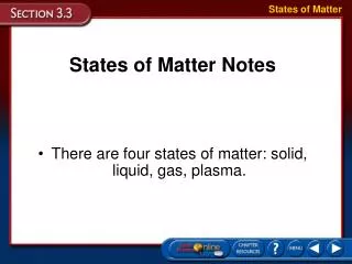
SLUDGE COMPOSITION • Predominantly water • Micro-organisms • Viruses, pathogens, germs in general • Organic particles, heavily bio-degradable • Organic compounds, inert, adsorpted to sludge flocs • Heavy metals • Micro-pollutants, pharmaceuticals, endocrine disrupters • All non-degraded compounds extracted from wastewater are found in the sludge
Sludge treatment alternatives Eckenfelder & Santhanam (1981)
Sludge thickening • Used to increase solid content of sludge by removing removing a portion of liquid fraction • Usually accomplished by physical means; e.g settling, flotation, centrifugation, gravity belt and rotary drum. • Why is it important? • Beneficial to the subsequent treatment processes from the following stand points: • Capasity of tanks and equipment required • Quantity of chemical required for sludge conditioning • Amount of heat (in digester) and fuel required for heat drying and incineration
Sludge thickening 2. Cost reduction -small pipe size and pumping cost 3. Liquid sludge can be transported easily • In designing thickening facility, it is important to: • Provide adequate capasity to meet peak demand • Prevent septicity, with its attendant odor problem.
Example • Estimate the sludge volume reduction when the sludge is thickened from 4% to 7% solids concentration. The daily sludge production is 100 m3. • Solution: • Calculate amount of dry sludge produced • Calculate volume in 7% solid content • Calculate percentage of sludge volume reduction Ans: 42.9%
EXAMPLE: • Primary sludge containing trickling filter humus is gravity thickened in circular tank with 3.6m dia. and 3 m side water depth. The applied sludge is 10 m3/d with 4.5% solids and the thickened sludge withdrawn is 5 m3/d at 7.5% solids. The blanket of consolidating sludge in the tank has a depth of 1 m. For odour control, 170 m3/d of treated wastewater is pumped to the tank along with sludge to increase overflow rate. Calculate: • Solid loading • % solid captured • Overflow rate • Solid retention time
STABILIZATION • Stabilization process of sludges for volume reduction, production of usable gas (methane), and improving the dewaterability of sludge • Solids and biosolids (sludge produced from primary or secondary treatment) are stabilized to: - reduce pathogens - eliminate offensive odors - inhibit, reduce, or eliminate the potential for putrefaction (decay, decompose of organic matters). Therefore, stabilization involves the reduction of volatile content and addition of chemicals to solid and biosolid and… Not suitable for survival of microb
Gravity Thickener Inflow Scum scimmer Sludge liquor Picket fence Thickened sludge
Processes in digester Anaerobic degradation Degradation of organic substances of app. 50% Biogas production: 63% CH4 (Methane) 35% CO2 2% other gases (N2, H2, H2S) electricity and heating Organic nitrogen is converged to NH4+ N-loading of WWTP
Characteristic values of digester Mean residence time of sludge Small units, badly mixed < 30 d Medium size units with mixing 20 d Large plants with mixing 12 – 16 d Biogas production related to degradation of organic substances 0.9 m3 / kg VSSdegr. Degradation of organic substances 40 – 55%
Simultaneous aerobic sludge stabilisation • No primary clarifier no primary sludge • High sludge age SRT, app. 25 d • Activated sludge tank is larger than that combined with an anaerobic sludge stabilisation • No biogas production • Possibly combined with storage or thickener unit • Stable and simple operation
Anaerobic Aerobic Organic loading rate High loading rates:10-40 kg COD/m3-day Low loading rates:0.5-1.5 kg COD/m3-day (for high rate reactors, e.g. AF,UASB, E/FBR) (for activated sludge process) Biomass yield Low biomass yield:0.05-0.15 kg VSS/kg COD High biomass yield:0.35-0.45 kg VSS/kg COD (biomass yield is not constant but depends on types of substrates metabolized) (biomass yield is fairly constant irrespective of types of substrates metabolized) Specific substrate utilization rate High rate: 0.75-1.5 kg COD/kg VSS-day Low rate: 0.15-0.75 kg COD/kg VSS-day Start-up time Long start-up: 1-2 months for mesophilic Short start-up: 1-2 weeks : 2-3 months for thermophilic Comparison between anaerobic and aerobic processes
Anaerobic Aerobic SRT Longer SRT is essential to retain the slow growing methanogens within the reactor SRT of 4-10 days is enough for the activated sludge process Microbiology Anaerobic processes involve multi-step chemical conversions and a diverse group of microorganisms degrade the organic matter in a sequential order Aerobic process is mainly a one-species phenomenon, except for nutrient-removal processes Environmental factors The process is more robust to changing environmental conditions The process is highly susceptible to changes in environmental conditions Comparison between anaerobic and aerobic processes
Sludge Digestion: Anaerobic
Volume reduction Water content in stabilised sludge > 95% ! Reduction of water content and volume Sludge volume With water content non-linear relation!
Volume reduction 12 Sludge treatment
Dewatering Conditioning with flocculation agents (poly-electrolytes) for efficient dewatering Unit Operation Method W DS Decanter Continuous Centrifuge > 0.7 < 0.3 Chamber filter press (large plants) Batch-wise Hydraulic pressure through plates in water-tight chambers > 0.6 ≤ 0.4 Belt filter press (small plants) continuous Pressed between two filter belts around staggered rollers > 0.7 ≤ 0.3
Drying bed • Thin sludge layer (< 20 cm) • Sand layer as drainage and filter layer • Sludge is first dewatered by drainage then air-dried through evaporation • Applicable for small plants Dimensioning W 0.55 (Imhoff, 1990) Plant type Specific surface Only mechanical treatment 13 PE/m2 Trickling filter 6 PE/m2 Activated sludge plant 4 PE/m2
Filling the drying bed with sludge Starting the drying process
Drying Vaporisation of water content Partial drying W 0.3 – 0.4 Full drying W down to < 0.1 Contact drying over heated areas Drying by convection through hot air counter-current inlet app. 600°C, outlet app. 300°C (Imhoff, 1999) For large plants Disposal is critical: fire, dust explosion In granulate form as fertiliser
Use in agriculture Recycling of nutrients, from stabilised sludge Sludge treatment Fertiliser* Liquid sludge P- and N-fertiliser Dewatered sludge P-fertiliser, N as storage product Dried sludge P-fertiliser * Limit re. over-fertilisation Problems • Acceptance • Heavy metals • Micro-pollutants, pharmaceuticals, endocrine disruptors
Composting Aerobic biological degradation of organic substances Prerequisites Stabilisation Dewatering Hygienisation Approach • Structure means: straw, wood, saw dust, wood chips • Mixture app. 1:1 • Water content app. 0,65 Requirements are more demanding than for sludge use as fertiliser!
Incineration Use of energy content, but not of nutrients Mono incineration (sludge exclusively) • Calorific value of sludge high enough no biogas use before, no stabilisation • Water content not minimised (no full drying) • Fluidised bed incinerator, incineration at 800 – 950°C in fluidised sand bed • Expensive! Co- incineration • In coal power station • In solid waste incinerators • In cement production, ash is bounded to cement