Download
1 / 46
460 likes | 481 Views
This guide provides an overview of the basics of probe diagnostics for cold, emissive, and heated probes in plasma physics. It covers topics such as flux of particles, ideal probe theory, and probe characteristics. Written by Roman Schrittwieser with contributions from other experts in the field.

E N D
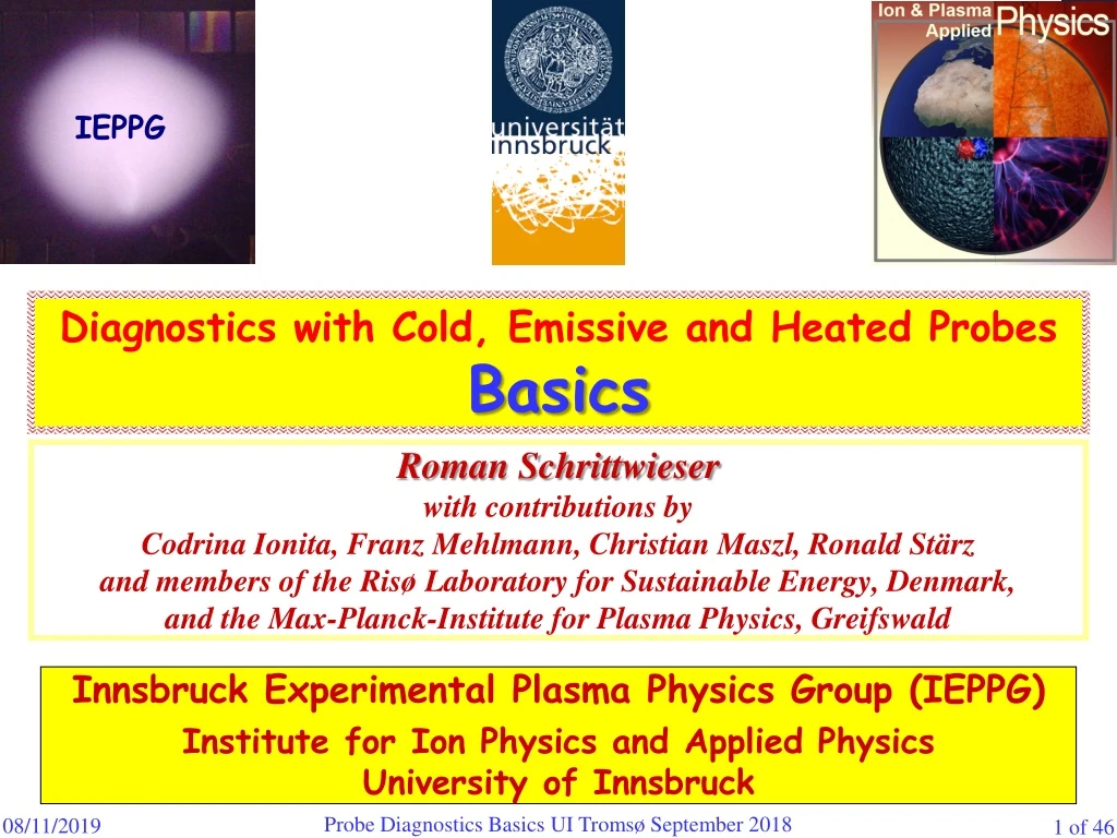
IEPPG IEPPG Diagnostics with Cold, Emissive and Heated Probes Basics Roman Schrittwieser with contributions by Codrina Ionita, Franz Mehlmann, Christian Maszl, Ronald Stärzand members of the Risø Laboratory for Sustainable Energy, Denmark,and the Max-Planck-Institute for Plasma Physics, Greifswald Innsbruck Experimental Plasma PhysicsGroup (IEPPG) Institute for Ion Physicsand Applied PhysicsUniversity of Innsbruck Probe Diagnostics Basics UI Tromsø September 2018
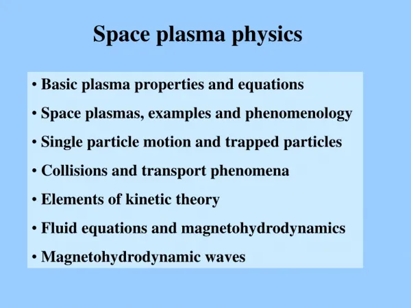
Contents Cold plane probes The flux of particles in gases and plasmas Ideal probe theory revisited Basic remarks The most important ranges and points in the characteristic Ion saturation current range A Electron retarding field region AC, the floating potential Band the plasma potential C The plasma potential C and the electron saturation current range Emissive probes Basic considerations The construction of an emissive probe and the heating circuit Measurement with emissive probes Laser-heated emissive probe A brief theory of emissive probes Probes in reactive plasmas Basic considerations Coating effects in a potassium plasma Other contamination effects on probes in a potassium plasma and how to avoid them by heated probes Probe Diagnostics Basics UI Tromsø September 2018
1.1. The flux of particles in gases and plasmas dA r Unit area dA with spherical coordinate system to calculate the particle flux towards it. (1.1) Probe Diagnostics Basics UI Tromsø September 2018
Maxwellian velocity distribution function (VDF) (1.2) Only half the density! (1.3) Volume element in velocity space d3v = v2 dv d2 = v2 dv sin d d (1.4) (1.5) = 1 = 2 Probe Diagnostics Basics UI Tromsø September 2018
(1.6) Three-dimensional random or thermal flux of particles (1.7) Mean velocity of a Maxwellian VDF (1.8) Random or thermal current density in a plasma (1.9) Random or thermal current to an area As (= surface of the probe sheath) (1.10) Probe Diagnostics Basics UI Tromsø September 2018
1.2. Ideal probe theory revisited Assumptions : • The plasma be infinite, isotropic and quasineutral. • Both charge carrier species have Maxwellian VDFs. • The size of our probe be negligible compared to the typical dimensions of the plasma and to the Debye length d. • The thickness of the sheath be small against the size of the probe so that the geometrical size of the probe area be approximately equal to the effective collecting area of the probe, which is the sheath edge. • The space charge sheath, which forms around the probe, have a well-defined boundary, outside which the plasma is unperturbed. • The mean free paths (MFP) for electron and ion collisions (among each other and with the neutrals) be large compared to the probe size and the thickness of the sheath. • Thus inside the space charge sheath there cannot be any ionisation and recombination processes, i.e., there is neither creation nor destruction of charge carriers within the probe sheath. • Every charge carrier, which reaches the probe, deliver there only its charge, but does not react otherwise with the probe surface and, if it is an ion, remains not on the surface. Probe Diagnostics Basics UI Tromsø September 2018
Ideal probe characteristic Ip(Vp) under the above assumptions in an unmagnetized plasma Ideal probe characteristic (current density versus probe voltage) for a potassium plasma with TeTi 0,2 eV with a density of ne ni 109 cm3. The dashed line shows the pure electron current density towards the probe (technical current direction), the dotted line the ion current density. The magnitudes of both currents decrease exponentially below, respectively, above the plasma potential pl (which here is assumed to be 2V) according to their respective velocity distribution functions. The solid line shows to total characteristic, which we obtain by adding both partial currents. Probe Diagnostics Basics UI Tromsø September 2018
Ip pl C D Schematic probe characteristic Ies Iis B Vp A (x) D: Vp > pl Plasma Probe C: Vp = pl x B: Vp = Vfl Potential profiles in front of the probe (schematically) A: Vp << pl Ip(Vp) = IeIi (1.11) Total probe current Above, schematic of the current-voltage characteris-tic of a single-sided plane probe; the points A to D refer to the lower part of the figure. Below, schematic of the potential profiles in front of the probe surface for four different cases as indicated. Probe Diagnostics Basics UI Tromsø September 2018
1.2.1. The different ranges of the probe characteristic: ForVppl : Boltzmann relation (1.12) Ii = Iis and (1.13) Total probe current A. Ion saturation current range, in which the value of the exponential function in Eq. (1.12) is close to zero: Ip = –Iis. B. The floating potential point where Vp = Vfl and where the ion and electron currents exactly cancel each other so that Ip = 0. Thus from Eqs. (1.11) and (1.13) follows: For floating probe (1.14) C. The plasma potential where Vp = pl and where there is no space charge sheath around the probe. There the value of the probe current is: Ip = Ies – Iis. D. The electron saturation current range where no ions can reach the probe anymore and where Ip = Ies. Probe Diagnostics Basics UI Tromsø September 2018
1.2.2. Ion saturation current range A: (1.15) Ion density at the edge of the real sheath! Ion-acoustic velocity to satisfy the Bohm criterion (1.16) (1.17) ni ni,ps x (1.18) Presheath pl Sheath Plasma Floating probe Vfl Probe Diagnostics Basics UI Tromsø September 2018
(1.19) (1.20) Child-Langmuir law Ion density: No real saturation in the beginning of the ion branch of the I-V characteristic! Probe Diagnostics Basics UI Tromsø September 2018
Probe with geometrical surface area Ap, ceramic-coated on the rear side Probe sheath with surface area As Schematic of a sing-le-sided plane probe with sheath in front, plasma and the wall with sheath in front as reference elec-trode; not in scale. For the idealised probe theory the probe sheath is assumed to be so thin that it can be neglected so that As Ap. Plasma Electrical probe connection Wall (= reference electrode) with sheath in front (x) x pl Space potential profile in front of the probe for floating or negatively biased probe (pl = 0) Vp Probe Diagnostics Basics UI Tromsø September 2018
1.2.3. Electron retarding field region AC, floating potential B and plasma potential C: Boltzmann relation: electron density insidethe sheath (1.21) For p(x) = Vp: (1.22) Electron density at the probe Random electron current outside the sheath (1.23) on the probe (1.24) Probe Diagnostics Basics UI Tromsø September 2018
Total probe current in electron retarding field region (1.25) (1.26) For Vp = Vfl: (1.27) (1.28) Floating potential Te determined from the difference between pland Vfl (1.29) Probe Diagnostics Basics UI Tromsø September 2018
Difference between plasma potential and floating potential (1.30) (1.31) Table 1 Probe Diagnostics Basics UI Tromsø September 2018
Determination of Te from the slope of the logarithmizedelectron retarding field current (1.32) (1.33) Probe Diagnostics Basics UI Tromsø September 2018
1.2.4. Plasma potential C and electron saturation current region (still ideal probe theory!): ForVp = pl: (1.34) Total probe current at plasma potential (1.35) In a realistic case, the effective areas of the probe for collecting ions and electrons might be strongly different Ratio between electron current and ion current at plasma potential (1.36/37) for Te = Ti: Probe Diagnostics Basics UI Tromsø September 2018
Thus electron current is always at least (1836)1/2 43 larger than ion current Therefore: Approximate probe current at plasma potential (1.38) Determination of the plasma density (1.39) Probe Diagnostics Basics UI Tromsø September 2018
2. Emissive probes Schematic characteristics of a cold probe in the edge region of a typical small tokamak; the general plasma parameters are the same in both cases: pl = +20 V, Te* = 10 eV, npl = 1012 cm3. (a) the electrons have no drift; (b) the electrons have a drift with a kinetic energy of eb = 40 eV. Probe Diagnostics Basics UI Tromsø September 2018
CP (positively biased) Plasma HP (a) Schematic of the conditions in a Q-machine plasma with a localised complex potential structure, specifi-callya double layer (DL) created inside. (a) schematic cross section of the Q-machine plasma column, (b) axial profile of the space potential in such a case, (c) conditions when a cold probe is inserted first in the position I and then in II with the sheath around it. pl z (b) pl,0 pl (c) e– z pl,0 I II Cold probe, biased at Vp = pl,0 Probe Diagnostics Basics UI Tromsø September 2018
Schematic characteristics of an emissive probe in the edge region of a typical small tokamak; the magnitude of the saturated electron emission current is adjusted to about twice the plasma electron saturation current; the general plasma parameters are the same in both cases: pl = +20 V, Te* = 10 eV, npl = 1012 cm3. (a) the electrons have no drift; (b) the electrons have a drift with a kinetic energy of eb =40 eV. Probe Diagnostics Basics UI Tromsø September 2018
Considerations : • The ion saturation current Iis can usually be neglected, especially in the case of an isotropic gas discharge plasma, where Ti often much smaller than Te. • But Ti can be approximately equal to Tem, the temperature of the emitted electrons, which have the same temperature as the heated filament from which they are emitted. The latter can hardly be higher than about 2500 K. • Seldom Tem and Te will be similar. Especially in gas discharge plasmas Tem << Te. Only in a Q-machine the temperatures can be almost identical namely about 2200 K. But if Te >> Tem, then the exponential drop of the magnitude of the electron emission current Iem will be much narrower than that of the plasma electron current Ie. • One serious problem for the emissive probe method might arise exactly from this problem, namely that Te >> Tem. Thus the mean flux of the latter is much larger than the mean flux of the former. This might lead to the formation on an electron-rich space charge around the probe collector, pulling the floating potential of the probe down. This can be under-stood by the fact that the emitted electrons have to be accelerated a bit in order to be really able to compensate the plasma electron flux. In such a case the emission current is no longer saturated and given by Richardson's law (and thus a function of the emissive probe temperature), but is determined by the potential difference between the plasma and the wire, and the Child-Langmuir law has to be taken instead for the emission current, which is then space charge limited. Probe Diagnostics Basics UI Tromsø September 2018
2.1. The constructionof an emissive probe andtheheatingcircuit: Richardson’s law for the unhindered emission of electrons from a hot me-tallicsurface (2.1) For the most often used material for emissive probe, namely tungsten, Ww is 4,55 eV and the Richardson constant is A* = 6,012105 Am2K2. Often also thoriated tungsten is used for emissive probe wires. This is tungsten alloyed with just about 0,2% thorium, which reduces the work function to about 2,63 eV, but also the Richardson constant drops to about 3104 Am2K2.Still the emission from a thoriated tungsten wire at the same temperature is stronger than from pure tungsten. Probe Diagnostics Basics UI Tromsø September 2018
Currents and particle fluxes around an emissive probe and the effect of a possible space charge formed by the emitted electrons on the emissive probe Electric currents Particle fluxes Plasma ions Plasma ions Plasma electrons Plasma electrons Emitted electrons Emitted electrons Space potential profile in front of the probe with saturated emission current Possible space potential profile in front of the probe with space-charge-limited emission current Space potential Space potential d x pl pl x 0.99Te Space charge due to emitted electrons Probe Diagnostics Basics UI Tromsø September 2018
The probe holder is a ceramic tube (Al2O3) of oval cross section (1,4/2,3 mm outer diameters) and a length of 8 cm. The tube has two bores of 0,7 mm diameter each. Inside the bores the tung-stenwires are spliced with thin copper threads to increase the conductivity. This guarantees that only the probe loop is glowing when a current is passed through. Schematic of an electron emissive probe as developed by the Innsbruck Experimental Plasma Physics Group and used in the CASTOR tokamak in Prague. Probe Diagnostics Basics UI Tromsø September 2018
Plasma Emissiveprobe Electronic regulation circuit:0 – 10 A, 0 – 10 V 7,5 A 12 V Pb-battery with 50 Ah ac amplifier to current-amplify the signal from the signal generator up to about 3 A Switch to change between the two modes of operation Signal generator, delivering a sawtooth frequency up to 10 kHz with about 15 V < 300 mA, 150 V Transformer, 1:10, for up to 10 kHz and 300 mA on the secondary side R 10 Sampling device (sampling rate about 100 kHz) Electronic circuit used for heating an emissive probe and for recording its current-voltage characteristic as used in the ISTTOK in Lisbon. The heating current is provided by a 12 V lead battery in order to avoid ground loops and other electromagnetic noises in the circuit. There are two possibilities to operate the circuit, once we can scan the current-voltage characteristic, or we can directly register the floating potential. Probe Diagnostics Basics UI Tromsø September 2018
2.2. A brief theory of emissive probes: For Vppl : Total probe current to (and from) and emissive probe Ip(Vp) = IeIiIem (2.2) Emission current (2.3a) (2.3b) Ii = Iis Ion current (= saturated) Electron current (= retarded) (2.3c) (2.4) Probe Diagnostics Basics UI Tromsø September 2018
For the floating case: (2.5) Floating potential (2.6) Difference between pl and Vfl (2.7) Floating potential (2.8) Difference between pl and Vfl (2.9) Probe Diagnostics Basics UI Tromsø September 2018
Theoretical dependence of the floating potential of an emissive probe for increasing heating current = emissive current according Eq. (2.9); shown is the difference em between the floating potential and the plasma potential, normalised to the electron temperature. (a) em versus the emissive current density jem normalised to the electron current density jes. (b) em versus the actual temperature of the wire Tw. Probe Diagnostics Basics UI Tromsø September 2018
When is the floating potential of the emissive probe equal to the plasma potential, i.e., when is em = 0? We remember Eq. (2.9): (2.12) As we have intuitively expected, this is the case when the plasma electron saturation current Ies is compensated by the sum of ion saturation current and electron emission current Iem + Iis. Probe Diagnostics Basics UI Tromsø September 2018
pl >> 0 pl 0 Ip Operating line for a sufficiently high input impedance Vp Wrong value for pl when input impedance is too low Operating line for an input impedance that is too low 2.3. Measurement with emissive probes: Schematic of two characteristics, one for pl 0 (solid line), one for pl>> 0 (dashed line). Also shown are two operating lines for two different input impedances, one sufficiently high (solid line), the other one too low (dashed line). What is actually measured is the intersection of the characteristic with the operating line. Probe Diagnostics Basics UI Tromsø September 2018
IEPPG 2.4. Laser-heated emissive probes: Together with the IPP Greifswald : A laser-heated probe has several advan-tages as compared to a conventional emis-sive wire probe: • Graphite or LaB6 can be heated to much higher tempera-tures, therefore higher electron emission and longer lifetime. • No current flows through the probe, therefore no danger of deformation in a magnetic field. • Lower capacity of the probe system, therefore better time response. • Surface of the probe is an equipotential area. A disk of LaB6 or graphite in the VINETA experiment (Greifswald) irradiated from above by light of 808 nm from a infrared diode laser (JenLas HDL50F from JenOptik, Jena, Germany) with up 50 W. Probe Diagnostics Basics UI Tromsø September 2018
IEPPG Prototype of a laser-heated probe for VINETA: Quartz window Glass fibre Head with lens system LaB6-probe Vacuum cylinder Magnetic field B [mT] 100 Plasma density [1019 m-3] ≤ 2 Electron temperature Te [eV] 3 Ion temperature Ti [eV] 0,2 VINETA Plasma Single bore Al2O3 tube Cu-wiresplicing Mo-wire Probe Diagnostics Basics UI Tromsø September 2018
IEPPG A radially moveable laser-heated probe : The diverging laser beam from the optical fiber is collimated by a first lens. It penetrates a quartz window into VINETA and is focused by a second lens onto the LaB6 or graphite pin of 1 mm diameter and 3 mm length. The second lens and the probe holder are mounted on the same radially movable shaft. Probe Diagnostics Basics UI Tromsø September 2018
IEPPG LaB6-pin:1,5 mm diameter, 3 mm length Ip(Vp)-characteristic of the laser-heated emissive probe with increasing laser heating power PL for radial position r–15 mm. The vertical green line indicates the value of pl,cold derived from the first derivative. The insert shows the zero-crossing of the characteristics in close-up. However, also for this case V*fl,em remains somewhat below pl,cold. We can easily reach emission currents of more than 2 A. Probe Diagnostics Basics UI Tromsø September 2018
IEPPG LaB6-pin:1,5 mm diameter, 3 mm length Floating potential of laser-heated probe versus laser heating power PL. Horizontal blue line shows pl,cold as derived from the first derivative of the cold characteristic. Also here we see that V*fl,em < pl,cold. There is an ongoing discussion whether or not the floating potential of a strongly heated emissive probe reaches the plasma potential or remains below. Probe Diagnostics Basics UI Tromsø September 2018
IEPPG LaB6-pin: 1,5 mm diameter, 3 mm length Floating potential of the probe versus laser heating power. The blue horizontal line shows the value determined from the inflection point of the cold characteristic. 15 mm outside the centre of the plasma column Floating potential of the probe versus laser heating power. The blue horizontal line shows the value determined from the inflection point of the cold characteristic.Centre of plasma column. As we have found out, sometimes the emissive floating potential even be larger than the value determined from the I-V characteristic of a cold probe Probe Diagnostics Basics UI Tromsø September 2018
3. Probes in reactive plasmas 3.1. Coatingeffects in a potassiumplasma: Schematic of a Q-machine, HP = hot plate, CP = cold plate, SG = signal generator, SA = Signal analyser. In this case, the central part of the cold plate has a diameter of 10 mm and serves as a kind of probe. It can also be heated by indirect electric heating. Probe Diagnostics Basics UI Tromsø September 2018
Particle flux in a magnetized potassium plasma, as example for technical plasmas Let us assume, we have a K-plasma with a floating cold plate, an average density of ni = 109 cm–3 and a plasma potential of pl = –2 V. We can easily calculate in this case that the minimum ion speed is 3130 m/s = 3,13105 cm/s. Thus a one-dimensional flux of ions of i = nivi 31014cm–2s–1flows along the magnetic field lines and eventually hits the cold plate. Assuming a small atomic radius of ca. 1 Å = 10–8 cm and therefore a cross section of about 3 Å2 = 310–16 cm2, then 31015 atoms are needed to create a monoatomic layer of potassium per cm2 on the cold plate. The results is that it just takes about 10 s to transform the clean tungsten cold plate into a cold plate that is completely covered by potassium so that the work function of the cold plate is no longer given by WW = 4,55 eV but by WK = 2,15 eV. Probe Diagnostics Basics UI Tromsø September 2018
Space charge sheaths Plasma Plasma Cold plate (W) Hot plate (W) Hot plate (W) Cold plate (W) Potassium coating pl pl WW WW WK z z pl pl Vfl = Vfl + (WWWK) ! Space charge sheaths Vfl* Schematic axial potential profiles along a Q-machine with clean hot plate and cold plate of tungsten (left-hand side) and with a K-coating on the cold plate (right-hand side). Probe Diagnostics Basics UI Tromsø September 2018
3.2 Other contamination effects on probes in a potassium plasma and how to avoid them by heated probes (C. Winkler, D. Strele, S. Tscholl, R. Schrittwieser, Plasma Phys. Contr. Fusion42 (2000), 217.) Schematic of an indirectly heatable tungsten cold probe, which can be heated to about 1000 K, thereby evaporating coatings by potassium and compounds so that the surface of the probe remains more or less clean. Shown are also the plasma source (hot plate) with the K-oven and the ion flow. Probe Diagnostics Basics UI Tromsø September 2018
Typical current-voltage characteristics of the indirectly heatable probe for various temperatures of the collector plate. Notice that in contrast to the characteristics up to now, the probe current axis is inverted, i.e., the electron current is displayed as a negative current. Probe Diagnostics Basics UI Tromsø September 2018
Calculated electron temperature Te as a function of the surface temperature T of the probe for increasing () and decreasing () heating power. The expected value for a hot plate temperature of THP 2220 K is Te 191 meV. Probe Diagnostics Basics UI Tromsø September 2018
Calculated values of V' = (c – pl) as a function of the probe surface temperature T for increasing () and decreasing () heating power. The plasma potential pl is constant during the measurement and has been determined independently by an emissive probe as –2,8 V. Probe Diagnostics Basics UI Tromsø September 2018
In a magnetized K-plasma the probe is not only exposed to a flux of potassium ions but also of residual gas atoms (in particular O2 and N2). • Thus on the probe surface chemical compounds especially of the oxygen and potassium can form, with the tungsten surface acting as a kind of catalyser. • Under our assumptions flux of potassium ions is K 61014 cm–2s–1, • Flux of residual gases is r 31014cm–2s–1(although the background pressure in the Q-machine is kept as low as possible). • For probe temperatures below 350 K, probe is covered by several monolayers of potassium (work function WK = 2,15 eV, pure tungsten WW = 4,55 eV). • Therefore apparent ´plis shifted by WWWK2,4 V. Corresponding contact potential 5,2 V. Contact potential decreases to about 1 V for higher probe temperatures (> T 400 K). This means the residual gas monolayer is left alone on the surface. (The desorption energy of K is about 1 eV). • To remove also the residual gas layer, we would have to heat the probe to temperatures of T 1900 K, which is not possible in our setup since the probe would become emissive (not wanted in our case). • Simultaneously the work function increases strongly. • In the range 400 < T < 600 K surface contamination is dominated by a combination of residual gas and potassium. The mobility of the adsorbed K-atoms is high enough to allow them to move around on the surface and to promote chemical reactions with the neighbouring residual gas atoms. Typical reactions are K + 2O KO2 and K + OH KOH, which both are exothermal, thereby enhancing the further desorption of the remaining potassium ions. Probe Diagnostics Basics UI Tromsø September 2018
Change W of the work function as a function of the probe surface temperature T for increasing () and decreasing () heating power. On the right hand side the corresponding values of the contact potential are indicated. Probe Diagnostics Basics UI Tromsø September 2018