Download
1 / 28
280 likes | 423 Views
Optical System Analysis on CCD Imager of the ISUAL Project. Chern-Fang Ho and A- Chuan Hsu ISUAL project Lab.of RF-MW Photonics, Department of Physics, National Cheng-Kung University, Tainan, Taiwan. Outline. Review on Instrument Requirements CCD imager Spectral filter

E N D
Optical System Analysis on CCD Imager of the ISUAL Project Chern-Fang Ho and A- Chuan Hsu ISUAL project Lab.of RF-MW Photonics, Department of Physics, National Cheng-Kung University, Tainan, Taiwan
NCKU UCB Tohoku CDR 9 July, 2001 Optical Simulation RF-MW Photonics Laboratory, NCKU
Outline • Review on Instrument Requirements • CCD imager • Spectral filter • Mechanical layout • Optical System analysis • Performance of CCD imager • Tolerance analysis • Stray Light Analysis • performance of CCD imager • Conclusions NCKU UCB Tohoku CDR 9 July, 2001 Optical Simulation RF-MW Photonics Laboratory, NCKU
Review on requirement of CCD imager NCKU UCB Tohoku CDR 9 July, 2001 Optical Simulation RF-MW Photonics Laboratory, NCKU
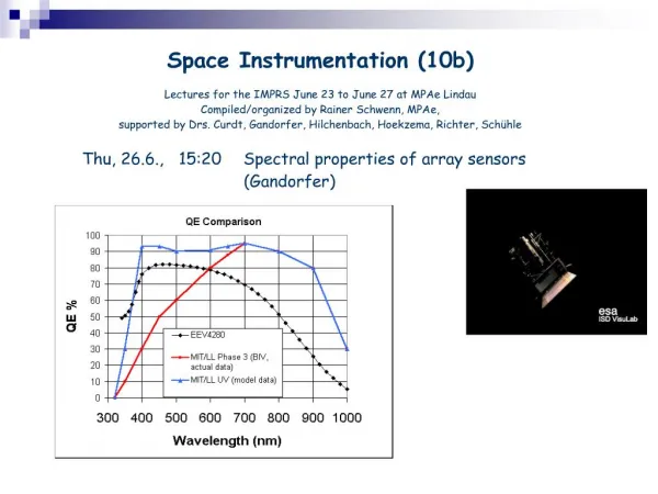
Review on spectral band of filters • 1.660-900nm • Noth @756-790nm • 2.762nm • 3.427.8nm • 4.630nm • 5.557.7nm • 6.400-900nm • IR/thermal block NCKU UCB Tohoku CDR 9 July, 2001 Optical Simulation RF-MW Photonics Laboratory, NCKU
Mechanical layout NCKU UCB Tohoku CDR 9 July, 2001 Optical Simulation RF-MW Photonics Laboratory, NCKU
Optical analysis results- Verification of Basic Requirements • Encircled energy of spot • 80% encircled energy in 40m diameter (Pixel Size) • See Spot diagram • Spatial Resolution • Nyquist Frequency(12.5cysles/mm)the max. spatial frequency of imager can be resolved by pixilated sensor • See MTF output NCKU UCB Tohoku CDR 9 July, 2001 Optical Simulation RF-MW Photonics Laboratory, NCKU
Spot Diagram ON AXIAL 0.7 field angle Full field angle Geometrical Spot size 0.007562 mm Geometrical Spot size 0.009436 mm Geometrical Spot size 0.01353 mm • Smaller than Specification limitation 0.02mm(rad) Scalar equal to Pixel Size(40*40m2) NCKU UCB Tohoku CDR 9 July, 2001 Optical Simulation RF-MW Photonics Laboratory, NCKU
Encircled Energy Encircled energy must be 80% in 40m diameter (Pixel Size) ON AXIAL 0.7 field angle Full field angle • 80% encircled energy : • 0.009149 mm(rad) • 80% encircled energy : • 0.011016 mm(rad) • 80% encircled energy : • 0.013974 mm(rad) • Smaller than Specification limitation 0.02mm(rad) NCKU UCB Tohoku CDR 9 July, 2001 Optical Simulation RF-MW Photonics Laboratory, NCKU
MTF output ON AXIAL 0.7 field angle Full field angle Geometric MTF at Nyquist Frequency Tan: 86.8% Sag: 79.6% Tan: 93.5% Sag: 93.5% Tan: 90.09% Sag: 90.01% Good output NCKU UCB Tohoku CDR 9 July, 2001 Optical Simulation RF-MW Photonics Laboratory, NCKU
Optical analysis results- Verification of Paraxial parameters Verification of the Basic Requirement NCKU UCB Tohoku CDR 9 July, 2001 Optical Simulation RF-MW Photonics Laboratory, NCKU
Real Condition Simulation • The imager will be working with different Spectral Filters • The Chromatic Focal shift will cause performance variation . • Defcous / Bluer in imager plane • We simulate the real condition and check the performance variation. NCKU UCB Tohoku CDR 9 July, 2001 Optical Simulation RF-MW Photonics Laboratory, NCKU
Chromatic Focal shift of Imager Lens System #2 defocus 0.03mm #3 defocus 0.01mm #4 defocus -0.07mm #5 defocus -0.1mm NCKU UCB Tohoku CDR 9 July, 2001 Optical Simulation RF-MW Photonics Laboratory, NCKU
Defocus and Bluer on Image Plane NCKU UCB Tohoku CDR 9 July, 2001 Optical Simulation RF-MW Photonics Laboratory, NCKU
Performance Variation in Different Spectral filter • Specification limitation of spots 20um(rad) NCKU UCB Tohoku CDR 9 July, 2001 Optical Simulation RF-MW Photonics Laboratory, NCKU
Image Diagram at Nyquist Frequency #2 Spectral filter #5 Spectral filter NCKU UCB Tohoku CDR 9 July, 2001 Optical Simulation RF-MW Photonics Laboratory, NCKU
Optical analysis results- Tolerance Analysis • Tolerance • Fabrication • Surface / Thickness / Index / V-number… • Component assembly error • Decenteration / Title / Air space… • Tolerance V.S. performance • Suitable tolerance • Performance variation NCKU UCB Tohoku CDR 9 July, 2001 Optical Simulation RF-MW Photonics Laboratory, NCKU
Optical analysis results- Component Tolerances of CCD imager • Imager lens system • 4 configuations for 4 different spectral filters • Consider component error • Air-space • Component decentation • Component center of curvature • Sensitivity analysis • Spot diagram / MTF tolerancing • Inverse sensitivity analysis • Suitable tolerance NCKU UCB Tohoku CDR 9 July, 2001 Optical Simulation RF-MW Photonics Laboratory, NCKU
Tolerance Guide of Imager lens system • High level precision in need NCKU UCB Tohoku CDR 9 July, 2001 Optical Simulation RF-MW Photonics Laboratory, NCKU
Stray light analysis Reflective rays of barrel Splits & Total internal reflections Ray Optical System Defocused GHOST IMAGES on image plane NCKU UCB Tohoku CDR 9 July, 2001 Optical Simulation RF-MW Photonics Laboratory, NCKU
CCD Imager Lens System Layout in ASAP Lens without barrel Lens with barrel NCKU UCB Tohoku CDR 9 July, 2001 Optical Simulation RF-MW Photonics Laboratory, NCKU
Investigation of Ghost Images • Raytracing - consider all split2 rays • Most significant ghost paths • For suitable simulation: • The ray split 2 times ( This is custom of ghost image analysis) • Consider the most significant ghost paths: depending on the energy or flux contributions on the image plane NCKU UCB Tohoku CDR 9 July, 2001 Optical Simulation RF-MW Photonics Laboratory, NCKU
Ghost image energy distribution Stray light tracing Ghost image spots On -axis 0.7 field angle Full field angle NCKU UCB Tohoku CDR 9 July, 2001 Optical Simulation RF-MW Photonics Laboratory, NCKU
MTF output MTF output is selected at Nyquest frequency 12.5 cycles/ mm • The ghost image will degenerate the MTF output. • The MTF still can keep a good output n(n-1)/2 ghosts for glass-air surface R is the loss for surfaces NCKU UCB Tohoku CDR 9 July, 2001 Optical Simulation RF-MW Photonics Laboratory, NCKU
Conclusion 1 - Optical System Analysis of CCD imager • We follow the setup of the “COATSAL OPTICAL SYSTEM,INC.” and simulate the imager lens system. We find: • The paraxial parameters are fit in with the specification of imager. • Good output performance (spot, encircled energy, MTF ) for postposition system. • But, if in real condition, the simulation shows that the performance of imager lens system will be degraded due to the Chromatic focal shift . • The imager works well for the #2 and #3 spectral filter. • But for the #4 and #5 spectral filer, the performance is poor, especially for the #5 filter, the imager only indicate the existence of object. NCKU UCB Tohoku CDR 9 July, 2001 Optical Simulation RF-MW Photonics Laboratory, NCKU
Conclusion 2 - Tolerance of Imager Lens System – Assembly Error • Based on the ISO10110 standard of tolerance and the Inverse sensitivity analysis we find: • the Imager needs high level precision in assembly. • if the assembly error occurs, the imager still work in #2 and #3 spectral filter, but the performance will degraded. For the cases of #4 and #5, the results becomes worse. • The imager need strong constructions (holder / spacer) to keep the lens system stable away from environmental variation. NCKU UCB Tohoku CDR 9 July, 2001 Optical Simulation RF-MW Photonics Laboratory, NCKU
Conclusion 3 - Stray light & Ghost image analysis • In current design, the signification ghost image should come from the split rays, i.e., from total internal reflection of lens media. • Contribution of the Ghost image are very small on image plane • about 0.1%~0.3% • the original MTF output performance remains NCKU UCB Tohoku CDR 9 July, 2001 Optical Simulation RF-MW Photonics Laboratory, NCKU
THE END NCKU UCB Tohoku CDR 9 July, 2001 Optical Simulation RF-MW Photonics Laboratory, NCKU