Download
1 / 23
250 likes | 384 Views
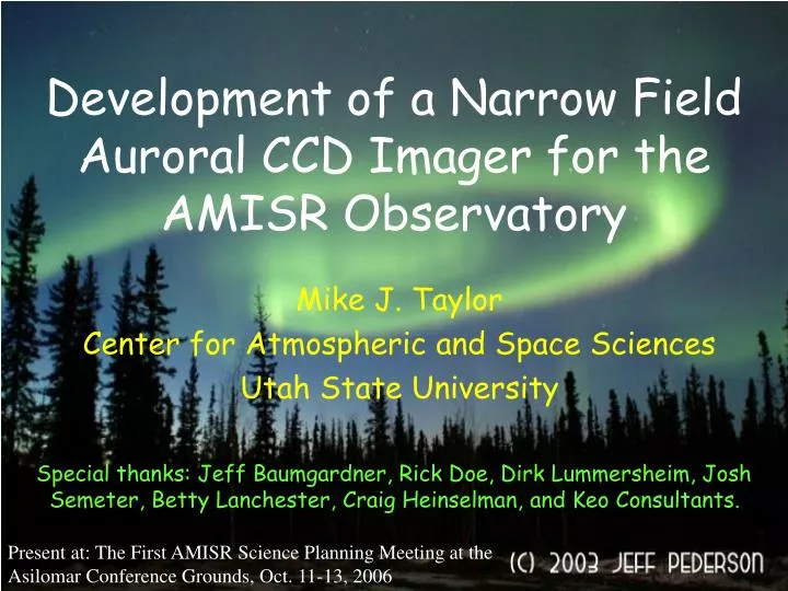
Development of a Narrow Field Auroral CCD Imager for the AMISR Observatory. Mike J. Taylor Center for Atmospheric and Space Sciences Utah State University. Special thanks: Jeff Baumgardner, Rick Doe, Dirk Lummersheim, Josh Semeter, Betty Lanchester, Craig Heinselman, and Keo Consultants.

E N D
Development of a Narrow Field Auroral CCD Imager for the AMISR Observatory Mike J. Taylor Center for Atmospheric and Space Sciences Utah State University Special thanks: Jeff Baumgardner, Rick Doe, Dirk Lummersheim, Josh Semeter, Betty Lanchester, Craig Heinselman, and Keo Consultants. Present at: The First AMISR Science Planning Meeting at the Asilomar Conference Grounds, Oct. 11-13, 2006
Outline • AMISR at PFRR. • Auroral imagery information. • Examples of coordinated radar and optical research. • “Straw man” camera requirements and design. • Data acquisition needs. • Infra-red imager for high latitude MLTI research.
AMISR • Two new facilities: • Resolute Bay, Canada. • Poker Flat, Alaska. • Solid state phased • array radar. • Rapid pulse to pulse • beam steering capability. • 3-D imaging of • ionospheric properties.
~ 580 km AMISR at PFRR Pointing: 74° elev., Azi. 15° E Field of view: ±25° (steerable) Full beam width: 1° (half power) Co-aligned optics: narrow field monochromatic auroral imager and CCD spectrometer.
Complimentary Imaging Capability • Essential context “big picture” information to aid and complement the interpretation of radar data. • High-resolution 2-D morphology and dynamics over a broad range of auroral forms. • Comparative measurements of different auroral emissions (energetics) using broad and narrow filters. • “Post-hoc” temporal-spatial photometry on selected narrow band auroral emissions. • Real-time data with “in field” pointing capability to enhance the selection of radar measurement volume.
Coordinated Radar and Optical Observations 30 Jan 1995: electric field vector • Wide Angle: 64° x 86° (90x160 km) • cut-off filter • 1 frame/3s • Electric field at 3s resolution North position of field-aligned beam West Electron Density Time (minutes) after 18:00 UT EISCAT Mainland Radar E-region: (Courtesy B. Lanchester, Univ. of Southampton)
EISCAT Movies Showing Electric Field Flip as Arc Crosses Radar ~ 1 min 20 sec. Higher spatial resolution
Summary N W 20 km Fine detail in electric field (3 second resolution)
EISCAT Svalbard Radar Coordination Field-aligned beam (0.7°) 17 Jan 2002 White light data FOV: 23° x 31° 25 fps (40 ms exposure) • Coherent scatter from ion acoustic waves • Structure size under 300 m at 500 km altitude • Varying on 0.2 second time scale • complicated spatial structure (<1 km) • fast temporal variations (<1 second) (Courtesy B. Lanchester, Univ. of Southampton)
examples of discrete auroral structures 0.1 to 1 km wide T.Trondsen (Univ of Calgary) Auroral Arc Fine Structure • Few instruments can measure it well • Few theoretical models can account for it (Courtesy B. Lanchester, Univ. of Southampton)
Vortex Structures From “NSF Passive Optical Report, 2005”
Observations: Properties of Discrete Aurora • Arc widths much less than 1 km • Lengths from several km to 100s or 1000s km • Multiple (parallel) curtains or filaments • Large field-aligned currents and magnetic perturbations • Strong velocity shear near discrete aurora • Large amplitude “spiky” electric fields in the acceleration • region • Time scales between fractions of seconds and minutes
Multi-Spectral Imaging of Discrete Aurora (<1keV el) 4278 7325 Semeter et al., 2001
AMISR Auroral Camera Capabilities Science Drivers: • High spatial resolution, <100-200 m (auroral fine structure). • Large dynamic range (discriminate faint auroral structures) • Broad spectral range (energetics of different emissions) • Low noise (high quality imagery of faint emissions) • Variable integration time (several frames per second to several seconds to accommodate broad range of auroral emissions) CCD Imagers: • Best option to achieve (most of) these goals. • High sensitivity, broad spectral range, low noise data.
Imager Field of View Shape: 100, 200, 300,400 km FOV Square FOV ? All CCD used but some light lost. Circular FOV ? Uses all light but no all CCD AMISR Poker Flat Size: For 30x30° rectangular field Zenith foot print at 100 km = 52 x 52 km CCD:1024x1024 = 50 m/pixel resolution (at 100 km)
Auroral Spectrum (From Space) Courtesy L. Broadfoot Potential Emissions: 427.8 nm N2+ (1NG) 486.1 nm H-beta (need to select 6) 520.1 nm NI 557.7 nm OI 589.3 nm NaI 630.0 nm OI 656.2 nm H-alpha 732/3 nm OII 750 nm N2 1PG (4-2,3-1) 844.6 nm OI Others? Help Please…….
QE-Bare CCD • Back thinned CCD: High QE over spectral range 400-850 nm • Excellent for narrow band imaging (<2nm) at visible wavelengths • Emission longer than ~700 nm will surfer etlonging effects (which • may be possible to remove later in software but not in real time).
Andor iKon-M Bare CCD Imager Active pixels: 1024x1024 Pixel size: 13x13 mm Imager area: 13.3x13.3 mm Back thinned peak QE: 95% Min. operating temperature: -80°C air, -100°C water Pixel well depth: 80,000 e- Pixel read-out rate: 2.5 MHz, 1MHz, 50 kHz Read-out noise: 2.5e-@ 50kHz 10 e-@ 2.5 MHz Digitization: 16-bit Dark Current: 0.0002 e-/pix/sec (-100°C) PC interface: USB 2.0 DU934N Max sustained data rate: ~ 2 images/sec at full resolution (~ 4 images/sec @ 512 x512 pixel resolution)
Andor iXon-EMCCD Imager Active pixels: 1024x1024 Pixel size: 13x13 mm Imager area: 13.3x13.3 mm Back thinned peak QE: 92.5% Min. operating temperature: -80°C air, -90°C water Linear EM gain: 1-1000 times Pixel well depth: 80,000 e- Pixel read-out rate: 10 MHz, 5MHz, 3MHz, 1MHz Read-out noise: 49e-@ 10MHz Digitization: 14-bit, 16-bit @ 1MHz Dark Current: 0.001 e-/pix/sec (-100°C) PC interface: PCI Mode (switchable): EMCCD or conventional Frame rate: 9 images/sec. (frame transfer with potential smearing of bright objects). LARGE DATA RATES!!! DU-888
Typical Telecentric Imager Design Courtesy Trond Trondsen
Straw man Design Requirements Telecentric lens system (for narrow band imaging) • FOV: 30x30° (to best match AMISR FOV) (Option 20x20° for higher spatial resolution) • Six position computer controlled filter wheel. • Three inch diameter, ~ 2 nm bandwidth interference filters. iKon camera: DU934N (1024x1024 pixel). • Spectral range: 400-900 nm. • Spatial resolution: 50 m at 100 km. • Frame rate: 2 images/sec. full resolution (normal operation: 4 images/sec.) • Investigating possibility of suppressed etalonging detector from E2V company.
Summary • Basic camera design based on well-proven airglow (and auroral) bare CCD imagers. • Primary role to provide high resolution imagery co-aligned with AMISR at PFRR. • System will be mount on steerable ALT-AZI tripod together with spectrometer. • Remote controlled operation of camera with onsite computer for data storage and real-time display. • Suggest this DU934 back thinned CCD as best option for a broad range of research with AMISR (typically operating at 512x512, 100 m resolution and frame rates ~ 4 per second to several second exposures) • Currently etalonging will limit NIR (>700 nm) narrow band imagery. • Future upgrading to EMCCD possible.