Download
1 / 13
130 likes | 248 Views
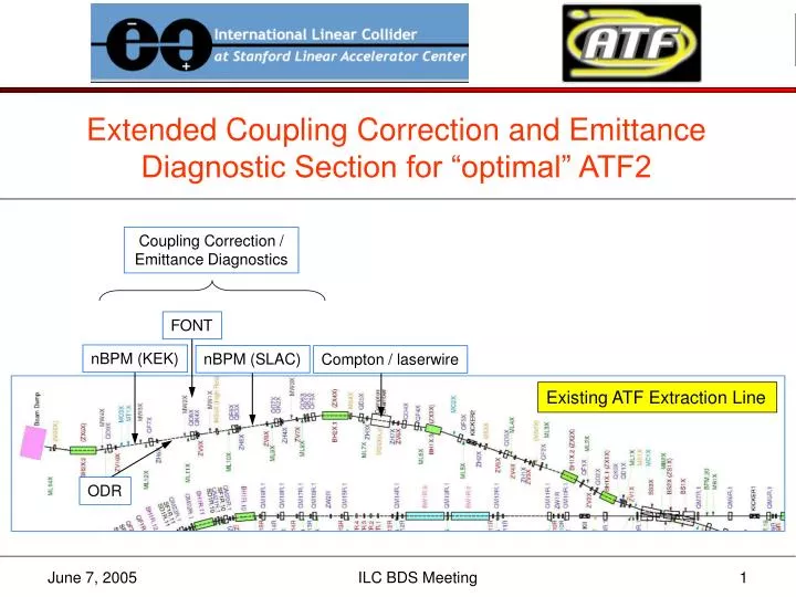
Extended Coupling Correction and Emittance Diagnostic Section for “optimal” ATF2. Coupling Correction / Emittance Diagnostics. FONT. nBPM (KEK). nBPM (SLAC). Compton / laserwire. Existing ATF Extraction Line. ODR. FF Optics Modifications. From Tauchi-san’s email ([bds 117] June 2, 2005):

E N D
Extended Coupling Correction and Emittance Diagnostic Section for “optimal” ATF2 Coupling Correction / Emittance Diagnostics FONT nBPM (KEK) nBPM (SLAC) Compton / laserwire Existing ATF Extraction Line ODR ILC BDS Meeting
FF Optics Modifications From Tauchi-san’s email ([bds 117] June 2, 2005): 5. Optics modifications: (1) concentrate on "optimal" design (straight) … done (2) change bends from sector bends to rectangular … done (3) use 0.8 m bends (as used in ATF) instead of 1 m for better field stability and more space … done (4) remove octupoles (do not use them, and they are tight) … done (OC0 removed; OC1 moved away from SF1) (5) extend diagnostics section (use up to ~10 m additional space) … done (6) QM14 is the strongest quad, and is close to max field of BT quads, need to check if its strength can be reduced by reoptimizing the matching section … done(QM14[K1L] = -1.1 m-1) ILC BDS Meeting
β*x,y = 4,0.1 mm ΔL = 7.1 m (w.r.t. baseline) 30 cm offset ILC BDS Meeting
Assembly Hall optimal baseline ILC BDS Meeting
+1% -1% ILC BDS Meeting
Coupling Correction • ideally • correction section with 4 independent skew quadrupoles, followed by • 2D (4 wire scanner) emittance measurement section • optics for orthogonal control of the 4 coupling phases • minimize εy once with each skew quadrupole • in present ATF extraction line • non-optimal optics in EXT straight section • wire scanners and skew quads interspersed • each wire scanner has x, y, and “u/v” (small angle, ~10°) wires • one attempt at full 4D beam matrix measurement and correction was inconclusive1 1 See http://atfweb.kek.jp/atf/Reports/ATF-99-01.pdf ILC BDS Meeting
“Ideal” skew correction / ε diagnostic section SQ SQ SQ SQ WS WS WS WS – x – y 90° 90° 180° 90° 90° 90° 45° 45° 45° 45° 45° 45° See http://www.slac.stanford.edu/cgi-wrap/getdoc/slac-pub-8581.pdf ILC BDS Meeting
SQ SQ SQ SQ 2.0 2.0 2.0 2.0 2.0 2.0 2.0 2.0 2.0 1.3 1.3 1.3 1.3 WS WS WS WS WS – x – y 90° 90° 180° 90° 90° 90° 33° 57° 57° 33° 33° 57° 57° 33° 59.2 10.8 108.0 5.9 59.2 10.8 108.0 5.9 59.2 10.8 σ (μm) For MAD files see http://www.slac.stanford.edu/~mdw/ATF2/optimal ILC BDS Meeting
new quadrupole (between QF3X and BH1X.3) ILC BDS Meeting
A ‘Drift’ e-Diagnostic Section from Paul Emma … b s L w1 w2 w3 3 wire scanners (or profile monitors) ILC BDS Meeting
– x – y σmin = 3 μm ILC BDS Meeting
Continuing Work • optimize system bandwidth and performance • add BPMs and dipole correctors • simulate steering and dispersion/coupling correction with machine/diagnostic errors • verify what space is needed for diagnostic equipment in chicane • investigate drift ε–diagnostic section • writeup for ATF2 proposal document ILC BDS Meeting