Download
1 / 77
820 likes | 1.33k Views
Plasma Fusion Energy Technology. S Lee 1,2,3 & S H Saw 2,1 1 Institute for Plasma Focus Studies 2 INTI University College, Malaysia 3 Nanyang Technological University/NIE Singapore. International Conference on Recent and Emerging Advanced Technologies in Engineering

E N D
Plasma Fusion Energy Technology S Lee1,2,3 & S H Saw2,1 1Institute for Plasma Focus Studies 2INTI University College, Malaysia 3Nanyang Technological University/NIE Singapore International Conference on Recent and Emerging Advanced Technologies in Engineering iCREATE 2009, 23 & 24 November 2009, Kuala Lumpur Malaysia
Outline of Talk • Introduction: The energy crisis • Nuclear Fusion Technology & energy • Tokamaks-early days to ITER & beyond • Alternative fusion programs • Plasma Focus technology into the future • Conclusion
STARS:- Nature’s Plasma Fusion Reactors Whilst above the white stars quiver With Fusion Energy burning bright
Plasma Physics: • Introductory: What is a Plasma? • Characteristics & high energy density
Introductory: What is a Plasma? Matter heated to high temperatures becomes a Plasma SOLID LIQUIDGASPLASMA Four States of Matter
Characteristics of Plasma State • Presence of electrons and ions • Electrically conducting • Interaction with electric & magnetic fields • Control of ions & electrons: applications • High energy densities/selective particle energies -Cold plasmas: several eV’s; (1eV~104K) -Hot plasmas: keV’s ; (1keV~107K) • Most of matter in Universe is in the Plasma State (e.g. the STARS)
Major technological applications • Surface processing, cleaning, etching, deposition • Advanced materials, diamond/CN films • Environmental e.g.waste/water treatment • High temperature chemistry • MHD-converters, thrusters, high power switches • Radiation sources: Microelectronics lithography • Medical: diagnostics, cleaning, instrumentation • Light sources, spectroscopic analysis, FP displays • Fusion Energy
The Singular, arguably Most Important Future Technological Contribution, essential to Continuing Progress of Human Civilization:- A NEW LIMITLESS SOURCE OF ENERGY
Scenario: World Population stabilizes at 10 billion; consuming energy at 2/3 US 1985 per capita rate Consumption Shortfall Supply Fossil, Hydro, fission
Plasma Fusion & the Future of Human Civilization A new source of abundant (limitless) energy is needed for the continued progress of human civilization. Mankind now stands at a dividing point in human history: • 200 years ago, the Earth was under-populated with abundant energy resources • 100 years from now, the Earth will be over-crowded, with no energy resources left
Without a new abundant source of energy Human civilization cannot continue to flourish. Only 1 good possibility: Fusion Energy from Plasma Reactors
Collisions in a Plasma The hotter the plasma is heated, the more energetic are the collisions
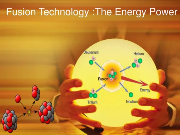
Nuclear Fusion If a Collision is sufficiently energetic, nuclear fusion will occur
Fusion Energy Equivalent • 1 thimble heavy water, extracted from 50 cups of water 50 cups water
Summary of Conditions Technological Targets: • T> 100 million K (10keV) • nt>1021 m-3-sec Two approaches: n=1020 m-3, confined t=10s (low density, long-lived plasma) or : n=1031 m-3, confined 10-10s(super-high density, pulsed plasma) Combined: ntT>1022m-3-sec-keV
Containing the Hot Plasma Long-lived low-density Confinement Pulsed High Density Confinement Continuous Confinement
Low Density, Long-lived Approach (Magnetic Compression) Tokamak • Electric currents for heating • Magnetic fields in special configuration for stability
Magnetic Yoke to induce Plasma Current Field Coils to Produce suitable Magnetic Field Configuration
JET (Joint European Torus) • Project successfully completed January 2000
Energy confinement time t scales as some functions of: • Plasma current Ip • Major Radius R • Minor radius ‘a’ • Toroidal Magnetic Field B scaling law: t~Ipa Rb ag Bl indices a,b,g,l all positive To achieve sufficient value of ntT requires: scaling of present generation of Tokamaks upwards in terms of: Ip, R, ‘a’ and B.
Fusion Temperature attained Fusion confinement one step away Needs x10 to reach ITER Needs another 2x to reach Power Plant
International Collaboration to develop Nuclear Fusion Energy-ITER • 1985- Geneva Superpower Summit: • Reagan (US) & Gorbachev (Soviet Union) agreed on project to develop new cleaner, sustainable source of energy- Fusion energy • ITER project was born • Initial signatories: former Soviet Union, USA, European Union (via EURATOM) & Japan • Joined by P R China & R Korea in 2003 & India 2005 • ITER Agreement- signed in November 2006
Systems: Magnets: Ten thousand tons of magnets: 18 extremely powerful superconducting Toroidal Field & 6 Poloidal Field coils;a Central Solenoid, and a set of Correction coils: magnetically confine, shape and control the plasma inside the toroidal chamber
Vacuum & Cryogenics Vacuum vessel: Volume=1400 m3Surrounding Cryostat vacuum jacket (not shown): Volume=8500 m3; Total vacuum volume~10,000 m3Largest vacuum volumes ever built; use mechanical & cryogenic pumpsVacuum vessel is double-walled with water flowing between the walls
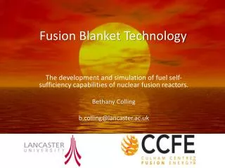
Associated with the vacuum vessel, advanced technological features include the following: • The Blanket: covers the interior surfaces of the Vacuum Vessel, provides shielding to the Vessel and the superconducting Magnets from the heat and neutron fluxes of the fusion reaction. The neutrons are slowed down in the blanket, their K.E. is transformed into heat energy and collected by coolants. This energy will be used for electrical power production. One of the most critical and technically challenging components: together with the divertor it directly faces the hot plasma. • Tritium breeding modules-in the first wall behind the front cover of the blanmket Breeding modules will be used to test materials for Tritium Breeding. A future fusion power plant will be required to breed all of its own Tritium. • The Divertor The Divertor is situated along the bottom of the Vacuum Vessel, its function is to extract heat and Helium ash — the products of the fusion reaction — and other impurities from the plasma, in effect acting like a giant exhaust pipe. It will comprise two main parts: a supporting structure made primarily from stainless steel and the plasma facing component, weighing about 700 tons. The plasma facing component will be made of Tungsten, a high-refractory material.
BLANKET: covers the interior surfaces of the Vacuum Vessel, provides shielding to the vessel & the superconducting magnets from the heat and neutron flux of the fusion reactionModular wall: 440 segments each 1x1.5m weighing 5 tons ; surface facing the plasma is plated with Berylium
Divertor: Is placed at bottom of the vacuum chamber To remove waste gases from the D-T reaction; and to recover the heat from this waste gas. The surface temperature of the divertor goes up to 3000 C; surface cover will be composite carbon or tungsten
An extensive diagnostic system (50 individual systems) installed to provide t measurements: control, evaluate & optimize plasma performance. Include measurements of temperature, density, impurity concentration, and particle &energy confinement times.
Cryostat: Large stainless steel structure surrounding the vacuum vessel & superconducting magnets, providing a supercooled vacuum jacket. Double wall, space between filled with pressurised He, as a thermal barrier.This is a huge structure: 31m tall x 37m wide; with openings for access to vacuum chamber, cooling systems, magnets, blanket and divertor
Plasma Heating • The temperatures inside the ITER Tokamak must reach 150 million C — ten times hotter than the Sun’s core- & be sustained in a controlled way in order to extract energy. The plasma in the vacuum vessel is produced and heated by a current induced by transformer action using a central solenoid (inner poloidal) coil, as primary of a transformer; the toroidal plasma current forms the secondary of the transformer Then 3 sources of external heating are used to provide the input heating power of 50 MW required to bring the plasma to the necessary temperature. 1. neutral beam injection 2. ion cyclotron heating & 3. electron cyclotron heating.
A "burning plasma" is achieved –in which the energy of the Helium from the fusion reaction is enough to maintain the plasma temperature. The external heating is then switched off. The plasma fusion burn continues.
ITER Construction has now started in Cadarache, France First plasma planned 2018 First D-T planned 2022
Q>10 and Beyond ITER : to demonstrate: possible to produce commercial energy from fusion.Q= ratio of fusion power to input power. Q ≥ 10 represents the scientific goal of ITER : to deliver 10x the power it consumes. From 50 MW input power to 500 MW of fusion power - first fusion experiment to produce net energy. Beyond ITER will be DEMO (early 2030’s), demonstration fusion power plant which will put fusion power into the grid as early as 2040
The other approach: Pulsed Super-high Density (Inertial Compression) • Radiation Compression
Pulsed Fusion: Radiation Compression • Radiation PressureCompression:Ignition:Burn: • e.g. powerful lasers fuel is compressed by density of fuel core Thermonuclear fusion • beamed from all rocket-like blow-off of reaches 1000 times spreads rapidly through • directions onto D-T hot surface material density of water super-compressed fuel • pellet (0.1mm radius) & ignites yielding many times • at 100 million K input energy
Cross-sectional view of the KOYO-F fast ignition reactor (Norimatsu et al.)