Download
1 / 21
280 likes | 826 Views
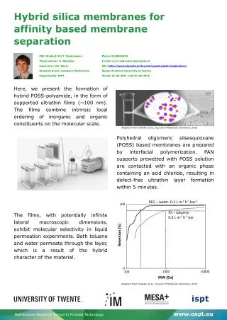
Oxygen separation with polymeric membranes. Dr. Ari Seppälä Department of Energy Engineering Applied Thermodynamics. Structure of lecture. About membranes Basics Different type of membranes Membrane structures Mass transfer phenomena inside membranes

E N D
Oxygen separation with polymeric membranes Dr. Ari Seppälä Department of Energy Engineering Applied Thermodynamics
Structure of lecture About membranes Basics Different type of membranes Membrane structures Mass transfer phenomena inside membranes Oxygen separation with polymeric membranes - Why separate oxygen and nitrogen? - Modeling boundary layers and gas separation in hollow fibre modules Based on fundamental differential balances of mass and momentum Based on mass transfer coefficients • Energy efficiency of oxygen separation • - Effect of selectivity and pressure ratio • - Pressurized vs vacuum mode • - Comparision of different oxygen production methods
Maxwell’s demon(by James Clerk Maxwell) p,T= constant -> Wm = work needed for separation of miscible components of a mixture (excluding the expansion work)
Transport coefficients for gas separation with membranes Permeability where D= diffusivity, S= solubility • Selectivity At a temperature of 20oC 1 Barrer corresponds to 8.16 ·10-13 m2/s. Note that the use of Barrer results in volumetric flux and m2/s in molar flux.
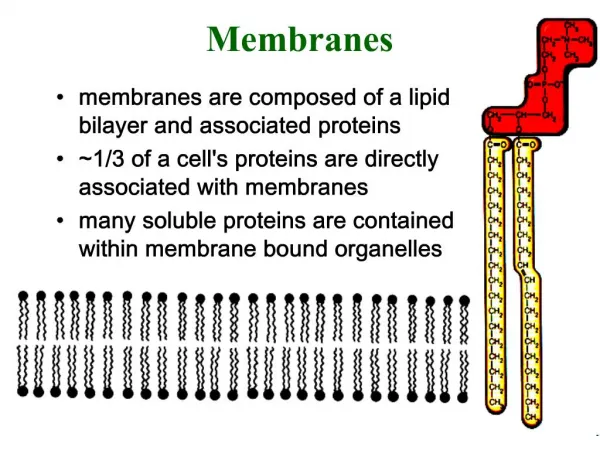
Polymeric membrane structures dense, non-porous layer porous, porous, with a porous dense, symmetric asymmetric substructure homogeneous, non-porous
Mass transfer through membranes convective +diffusive flow Knudsen diffusion molecular sieving and surface diffusion macroscale microscale (gases) nanoscale (gases) phenomenon
Mass transfer through membranesSolution-diffusion (SD) model dissolved free volume motion of the free a diffusion jump has penetrant element volume elements been performed
Solution-diffusion (SD) model and boundary layers ki,s ki,l Solubility Si ki,m δ δ δ δ δ δ δ δ δ δ δ δ superscripts:F=feed, P=permeate (product), subscripts: m=membrane, s=shell, l= lumen
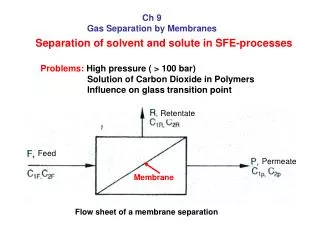
Gas separation with membranes which transport is based on solution-diffusion model Partial pressure (pi) difference is the driving force Total pressure pF at feed side (F) must exceed the total pressure PP at the permeate side (P): Separation is based on different permeabilities of the species, i.e. selectivity must differ from α= 1.
Solving velocity and concentration boundary layers in fluids– fundamental method (model II) Liquid phase Gas phase Continuity of mass Continuity of species i Momentum equation Incompressible Navier-Stokes Weakly compressible Navier-Stokes + SD-model +boundary and intial conditions u=velocity of mixture,p=pressure, ω=mass faction,μ=viscosity,ρ=density, t=time, j=diffusion flux
Solving boundary layers – correlation based approach (model I) shell side permeate lumen side feed residue • axial flow direction: convection/advection>>diffusion -> diffusion can be neglected • radial flow direction: serial resistance model accouning for transport through membrane and lumen and shell side boundary layers For detailed description and equations, see: Meriläinen, Seppälä, Kauranen, Applied Energy 94 (2012) 285-294
Nagasep-module applied in experiments Figure 12. Nagasep M60-AS module.
Comparison of models and experiments Gas-water Deoxygenation of water with a vacuum pressure of 0.02 bar on the shell side
Boundary layers based on model II Gas-Gas In this case, boundary layer effect in both gas phases is minimal -> oxygen transfer is limited almost completely by the resistance of the membrane! Molar fraction profiles of oxygen and nitrogen across the fibers at z = 0 in counter-current flow. Stage cut θ = 0.07. pF = 3 bar, pP=1 bar.
Boundary layers based on model II Gas-Gas feed air (3 bar) residue permeate (1 bar) Oxygen concentration (mol/m3) in the three phases and streamlines illustrating oxygen flux in the shell of the module. Stage cut θ = 0.70. pF = 3 bar. Note! Oxygen concentration is smaller in the permeate than in feed because the total pressure of peremate is lower. Permeate is enriched with oxygen.
Boundary layers based on model II Concentration profiles of dissolved oxygen in water in the fiber lumen with varying feed water velocities. Atmospheric air flows through the shell of the module and gases are transported through the membrane into water. T = 25 ºC. Gas-water v = 2 cm/s 5 cm/s 10 cm/s 20 cm/s 50 cm/s water air