Download
1 / 26
270 likes | 625 Views
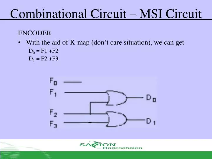
Combinational Circuit – MSI Circuit. ENCODER With the aid of K-map (don’t care situation), we can get D 0 = F1 +F2 D 1 = F2 +F3. Combinational Circuit – MSI Circuit. ENCODER (Octal to Binary) At one time, only one input line has a value of 1 Most of the time needs priority encoder.

E N D
Combinational Circuit – MSI Circuit ENCODER • With the aid of K-map (don’t care situation), we can get D0 = F1 +F2 D1 = F2 +F3
Combinational Circuit – MSI Circuit ENCODER (Octal to Binary) • At one time, only one input line has a value of 1 • Most of the time needs priority encoder
Combinational Circuit – MSI Circuit ENCODER (Octal to Binary) • Can you get 2n to n encoder without using Karnaugh map
Combinational Circuit – MSI Circuit DEMULTIPLEXER • Given input line & sets of selection line, demultiplexer will send data directly from input to selected output line • Example: 1 to 4 Demultiplexer
Combinational Circuit – MSI Circuit DEMULTIPLEXER • Demultiplexer is similar to decoder with enable as follows:
Combinational Circuit – MSI Circuit MULTIPLEXER • multiplexer is a device which consist of • Several input line • Several select line • One output line • It transmit one from 2n input line to one output line using n select line. It is also known as data selector
Combinational Circuit – MSI Circuit MULTIPLEXER • Truth table for 4-1 multiplexer
Combinational Circuit – MSI Circuit MULTIPLEXER • Output for multiplexer is Sum of the (product of data lines and selection lines) • Example: Output for 4-1 multiplexer is • 2n-to-1 line multiplexer or 2n:1 MUX is made from n:2n decoder with 2n input line added, for each AND gate.
Combinational Circuit – MSI Circuit MULTIPLEXER
Combinational Circuit – MSI Circuit MULTIPLEXER • Usage:
Combinational Circuit – MSI Circuit LARGE MULTIPLEXER • Large multiplexer can be built from smaller multiplexer • 8:1 multiplexer can be built from smaller multiplexer like this
Combinational Circuit – MSI Circuit LARGE MULTIPLEXER • Other example the building of 8:1 multiplexer from smaller multiplexer
Combinational Circuit – MSI Circuit LARGE MULTIPLEXER • 16:1 multiplexer can be built using five 4:1 multiplexer
Combinational Circuit – MSI Circuit MULTIPLEXER (Function Execution) • Boolean Function can be executed using multiplexer • 2n:1 multiplexer can execute Boolean function with n input variable as the following • Expression in SOM Example: • Combine n variable to n selection line • Put 1 at data line if it is a minterm for that function, else 0
Combinational Circuit – MSI Circuit MULTIPLEXER (Function Execution) • This method succeed because • Put 1 at I1,I2, I3, and 0 at the remaining
Combinational Circuit (Programmable Logic Device) Read-Only-Memory (ROM) • Semiconductor memory is a device where data can be stored and fetched • Logically, this memory device can be said as memory cells table (data)
Combinational Circuit (Programmable Logic Device) Read-Only-Memory (ROM) • ROM is a memory device where data can only be read but cannot be written • Writing is done by special programming device (programmable ROM) • Any Boolean function can be executed by using ROM. The steps: Get TT, take its input as address and output as data • Advantage: Boolean function is executed directly • Disadvantage: Didn't use the “don’t care” and variable input numbers is limited (e.g. 10 input – 1K, 16 input – 64K, 20 input – 1M)
Combinational Circuit (Programmable Logic Device) Read-Only-Memory (ROM) • Ready-made ROM Device Type • ROM: Read Only Memory Data is written to memory by “mask programming” when manufacturing process. High cost to start and very cost effective if produced in large quantity • PROM: Programmable ROM Semi-custom chip. Fuse can be burnt with “special hardware programming unit”. High cost for small quantity and it cannot be erased after programmed.
Combinational Circuit (Programmable Logic Device) Read-Only-Memory (ROM) • Ready-made ROM Device Type • EPROM: Erasable PROM Similar with PROM only that data can be erased by exposing it to ultra violet light • EEPROM: Electrically EPROM PROM where data to be erased can be selected by “hardware programmer unit” other than ultra violet light. Very useful for isolated device where it can be reprogrammed from far
Combinational Circuit (Programmable Logic Device) Programmable Read-Only-Memory (PROM) • Device with hardwired AND array (i.e. decoder) and programmable OR array • AND array (decoder) execute 2n minterm product combination for n input (known as n:2n decoder) • n line input and m line output • Input bit variable combination – address • Input bit combination for output line – word (each word contain m bit)
Combinational Circuit (Programmable Logic Device) Execute logical function with PROM • Example (8X3 ROM) – • First, convert each function to SOP


![G6 - CIRCUIT COMPONENTS [3 exam question - 3 groups]](https://cdn1.slideserve.com/2780393/g6-circuit-components-3-exam-question-3-groups-dt.jpg)